Trench
This file contains the trench identifier and the 3D coordinates of the start points, inflection points, and end points of each surveyed trench. Sample boundaries do not need to correspond to fixed points in a trench. The function will “wrap” samples around corners and angles.
![]()
The same option is available on the Grade Copilot tab, in the Generate group.
An example of the Trench Control file generated by this function is:
Trench Survey
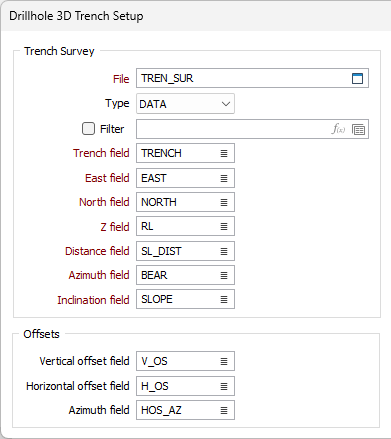
File
Double-click (or click on the Select icon) to select the name of the Trench Survey file containing your data. If required, define a filter to selectively control which records will be processed.
Enter the names of the required fields in the Trench Survey file.
Trench ID field
Specify the names of the field that identifies each trench in the Trench Survey file.
East and North and Z fields
Specify the names of the fields containing Easting, Northing, and Z coordinates in the Survey file. In the X, Y, Z coordinate system, these are the X , Y and Z directions.
Distance field
Enter the name of the field containing the slope distance between positioning points.
Azimuth field
Specify the name of the field containing values which define the azimuth direction of the trench in decimal degrees. Conventions are: 000.00 degrees for North, positive values increase clockwise from the North. Negative values and values greater than 360° are correctly evaluated.
Inclination field
Specify the name of the Inclination field. Inclination values are expressed in degrees from -90 to 90, with negative values representing downward inclines.
Offsets
Any number of points, including the Reference Point, may be offset. Offsets are required when a point in the trench can not be defined for the Distance, Azimuth and Inclination fields. For example, when the trenches are full of water or have collapsing walls.
In such cases the Distance, Azimuth and Inclination fields define the position of the offset point from the last point in the trench. The Vertical offset, Horizontal offset and the Azimuth offset prompts define the bearing FROM the offset point TO the actual trench point.
Vertical and Horizontal Offsets
(Optional) If the Trench Survey file contains points offset from the actual survey points, enter values in Vertical offset, Horizontal offset.
Azimuth Offset
Enter a value to define the bearing FROM the offset point TO the last (real) trench point.
Assays
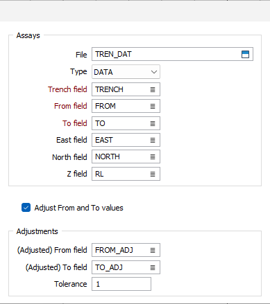
File
Double-click (or click on the Select icon) to select the name of the Trench Survey file containing your downhole data. Hole or Trench; From and To; and one or more assay fields must be present in the file.
Trench ID field
Specify the names of the field that identifies each trench in the Assay file.
East and North and Z fields
Specify the names of the fields containing Easting, Northing, and Z coordinates in the Survey file. In the X, Y, Z coordinate system, these are the X , Y and Z directions.
From and To fields
Specify the names of the From and To fields in the Assay file. The To value is always greater than the From value and the difference between them (To - From) is the length (or thickness) of the interval.
Adjustments
In some cases the total length of the trench calculated using the sum of the slope distances will vary from the total length of the trench defined by the maximum To value. If this difference exceeds the tolerance you enter, an adjusted From-To value will be written into the nominated fields in the Assay file. You must create these fields.
If you select Adjust From and To values, the program automatically creates the fields: FROM_ADJ and TO_ADJ and writes the adjusted values to them.The adjustments are prorated over the entire length.
Typically, you will use this function to create surface trench files that can be used with Display | Trench Display. However, it works equally well for underground channel samples that follow drive walls, and for face sampling.
Adjusted From and To Fields
(Optional) If you need to adjust the last From-To value when the length of the trenches as defined in the Trench Survey file is different from that defined by the last To values in the Assay file, select Adjust From and To values check box and enter a Tolerance.
The fields, FROM_ADJ and TO_ADJ will be created in the Assay file and the adjusted values written to them. If you do not select Adjust From and To values, enter a Tolerance and the names of the fields where the adjusted values will be written.
Select additional Validation options where necessary.
Validation
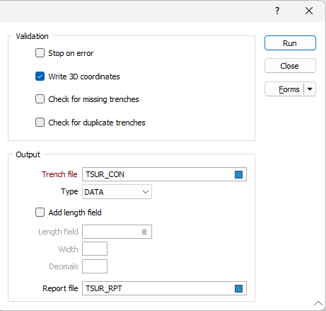
When you run Trench Coordinates, it validates the input data. You should only generate 3D coordinates once the input data is correct (Write 3D coordinates? must be selected before 3D coordinates will be generated). When you are validating the input data, you should use a Report file for any errors. For a Report file to be generated, you must enter a name in the Report file response. In general, the validation rules for trenches are the same as those applied to the Drillhole functions.
The following validation options can be selected for more rigorous checks.
Validation options
Select the Stop on error option when you want to stop processing when an error occurs.
The Write 3D coordinates option is selected by default. But you should only generate 3D coordinates once the input data has been validated and is considered to be correct.
Select the Check for missing trenches option to check for missing trenches in the file. You will usually perform this check once per dataset.
Select the Check for duplicate trenches option to check for duplicate Trench IDs in the file.
Output
Trench file
Double-click (or click on the Select icon) to select the name of the Trench Control file that will be created as a result of running the function. The calculated coordinates of inflexion points will be written to this file.
Select the Add Depth field check box option, if you want depth values to be written to the control file. Specify the Name, Width and Precision of the Depth field.
Report file
Double-click (or click on the Select icon) to select the name of a Report file where a summary of the process will be written.
Run
After validating your data, ensure that the Write 3D coordinates and click the Run button to run the function.