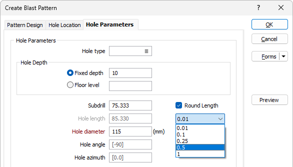
Hole Parameters
Use the Hole Parameters tab of the form to define the depth and direction of the holes in the pattern.
Hole Parameters
Some of the following parameters are optional but should be specified if you intend to calculate explosive or stemming lengths.
Depth
Enter the depth for the holes in the drillhole pattern.
Subdrill
Enter the depth to which the blastholes will go below the planned grade or floor level, in metres, i.e. the length of sub-drilling required.
Hole Diameter
Enter a value in millimetres. The value must be entered. Hole diameter is a fundamental factor in blast geometry since it affects the results that can be achieved from blasting.
Excellent energy distribution can be achieved using blasthole diameters (mm) which are equal to the bench height (m) multiplied by 8 to 15. d = (8 to 15) x BH
WHERE:
d = Hole diameter (mm)
BH = Bench Height (m)
For example, for a bench height of 5m:
d = (8 to 15) x 5
d = (8 x 5) to (15 x 5)
d = 40 to 75mm
Hole Type
Holes may be blasted for different purposes. You may want to differentiate between main, pre-splitting and auxiliary holes, for example.
If applicable, select the Hole Type. Hole types are configured on the Mining | Blast Design tab, in the Hole Type group.
Hole Angle
The Hole angle is the angle the hole makes with the azimuth, in the range 0 (horizontal) to - 90 (vertical). If no values are specified, a default inclination of -90 (vertical) and a default azimuth of zero are used.
Hole Azimuth
The Hole azimuth is a bearing in degrees, measured from 0 for North and increasing clockwise. It will have no effect on a vertical hole (inclination of - 90).
Round Length
If you select the Round Length option, you can use the drop down to select the rounding to be applied to the blastholes when creating the pattern.
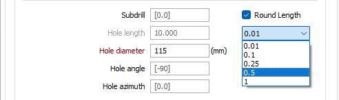
The selected rounding option will be applied to the Length value for the blastholes in the pattern.
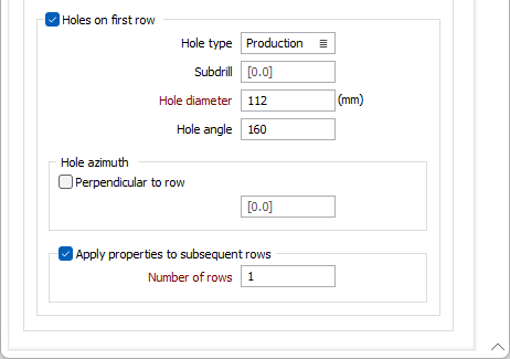
Holes on first Row
The Subdrill, Hole Diameter, Hole Type and Hole Angle parameters (described above) can be set separately for holes on the first row.
An Azimuth value can be entered to allow sloped holes on the first row to have a user defined azimuth. Alternatively, select the Perpendicular to Row check box.
A check box can also be set to Apply the above properties to subsequent rows. When this check box is selected, the specified number of rows (after the first row) will have the same properties as those defined for the holes on the first row.
Enter the number of subsequent rows.