Row (Insert Hole, Add, Extend)
On the Blast Design ribbon in the Drillhole Pattern group, the same form is used by the following tools to achieve slightly different results:
-
Click Add Row to add a new row to a blast block. Hole, location and charge parameters can be specified beforehand in an Row Properties form. See: Add Row

-
Click Extend Row to add new holes to an existing row by snapping to a point on that row. Hole, location and charge parameters can be specified beforehand in an Extend Row form. See: Extend Row

-
Click Insert Hole to insert or append a hole to an existing row. Hole, location and charge parameters can be specified beforehand in an Insert Hole form. (See Below.)

Insert Hole
On the Mining | Blast Design tab, in the Drillhole Pattern group: Click Insert Hole to insert or append a hole to an existing row. Hole, location and charge parameters can be specified beforehand in an Insert Hole form.
![]()
Hole Parameters
Hole type
Holes may be blasted for different purposes. You may want to differentiate between main, pre-splitting and auxiliary holes, for example.
If applicable, select the Hole Type. Hole types are configured on the Mining | Blast Design tab, in the Hole Type group.
Hole length
Enter the Hole Length value for the holes along the new row in the field provided.
Subdrill
If blastholes are to be drilled below the design floor, enter the length of sub-drilling required. See: Sub-Drilling
Hole diameter
Enter the diameter (in millimetres) for the holes along the row. Hole diameter is a fundamental factor in blast geometry since it affects the results that can be achieved from blasting.

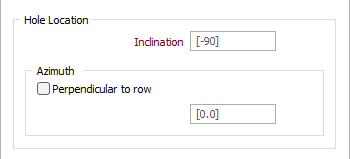
Hole Location
Enter parameters to define the Inclination, Spacing and Azimuth of the holes along the row.
Inclination
The hole Inclination is the angle the hole makes with the azimuth, in the range 0 (horizontal) to - 90 (vertical). If no values are specified, a default inclination of -90 (vertical) and a default azimuth of zero are used.
Azimuth
The hole Azimuth is a bearing in degrees, measured from 0 for North and increasing clockwise. It will have no effect on a vertical hole (inclination of - 90). The Perpendicular to row check box option allows you to specify an azimuth which is perpendicular to the row.
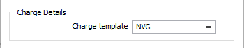
Charge Details
Charge Template
Double click (F3) in the Charge Template field, or click the List icon, to select a charge template for the row, if required.
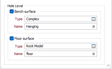
Hole Level
The designed blastholes can be draped onto a wireframe of the topography. The draping can be to the Bench and/or the Floor.
Bench Surface
Select the Bench surface option to select a wireframe Type and Name to drape the blast hole onto.
If the Bench surface is not selected and provided,
Floor Surface
Select the Floor surface option to select a wireframe Type and Name to drape the blast hole onto.
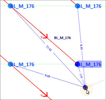
About Distance Annotations
When interactively editing the location of a hole, annotations are displayed to show the distance between the hole being moved and its three closest holes and also the distance between the hole being moved and its original location.