Rectangular Pattern
![]()
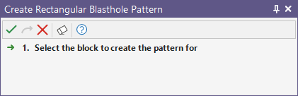
If a block is not already selected, you will be prompted to select one:
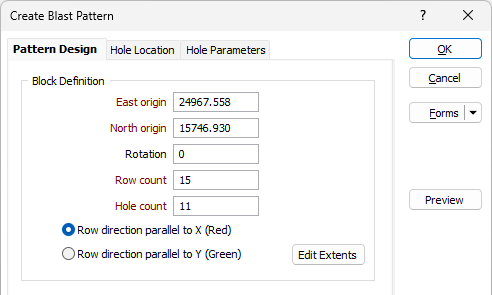
Use the Pattern Design tab of the Create Blast Pattern form, to define a basic rectangular, staggered, or triangular blast pattern.
Block Definition
Define the Origin, Rotation and Direction of the pattern.
East origin/North origin
Initial East origin/North origin default values are calculated from the current block. If necessary, modify the East origin and North origin values.
Rotation
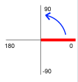
Define the rotation of the bounding rectangle. The rotation angle starts from a 90° (right) direction and is measured anti-clockwise.
Row count/Hole count
Initially, the number of rows and the number of holes is calculated from the current block extents and from hard-coded Spacing and Burden default values. Accept the defaults or enter the number of rows and the number of holes.
You can visually adjust the extents of the pattern by clicking Edit Extents (See below).
Row direction
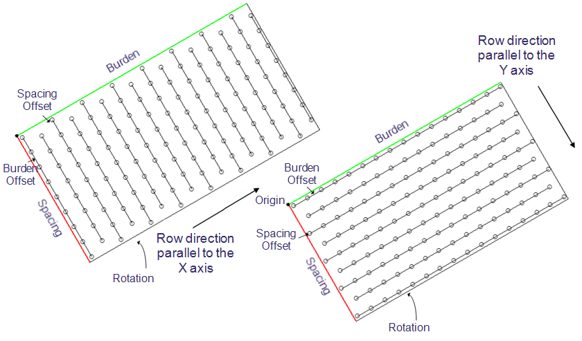
Specify whether the row direction will be ![]() parallel to the X axis (the default) or
parallel to the X axis (the default) or ![]() parallel to the Y axis. The axes of the blasthole boundary are labelled by Burden and Spacing and the colours drawn on the axes are consistent with the 3D orientation axis in Vizex:
parallel to the Y axis. The axes of the blasthole boundary are labelled by Burden and Spacing and the colours drawn on the axes are consistent with the 3D orientation axis in Vizex:
- Red is the colour for the X-axis:
- Green is the colour for the Y-axis:
Edit Extents
Click the Edit Extents button to collapse the form and visually adjust the extents of the pattern. Interactively adjusting the extents rectangle in Vizex will update the values in the form.
Pattern
Choose whether the blasthole spacing is Rectangular, Staggered or Triangular. A staggered or triangular drilling pattern is generally considered more efficient than a square or rectangular pattern. See: Patterns
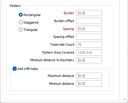
Burden and Spacing
Initial Burden and Spacing default values are hard-coded.
The Burden distance will generally lie between 20 to 35 times the hole diameter depending on the rock density and the explosive charges used. The Spacing distance between blastholes is generally between 1 to 1.8 times the burden, with 1 used for very hard massive rock and 1.8 for very soft or well-jointed rock. See: Burden and Spacing
Note that Burden and Spacing distance values cannot be negative or zero values.
Burden Offset and Spacing Offset
If there is no Burden offset or Spacing offset, then the first blasthole has the Easting and Northing value of the boundary origin.
Note that the reported pattern area corresponds to the area covered by the drillholes in the pattern.
-
When a Burden Offset is entered, the first and last row of the pattern are adjusted to maintain the specified offset distance from the adjacent sides of the grid.
-
When a Spacing Offset is entered, the first and last holes in each row are adjusted to be the specified offset distance away from the adjacent ends of the pattern.
Total Hole Count
Displays the total number of holes that will be in the pattern based on the design parameters. The value will be updated as changes are made to the design parameters.
Pattern Area Covered
Displays the total area of the pattern based on the design parameters. The value will be updated as changes are made to the design parameters.
Minimum Distance to Boundary
Specify the minimum distance between the block boundary and the first/last hole of a row. This value is also taken into account when the Add infill holes check box option is selected (below).
Add Infill Holes
Select this check box to add infill holes.
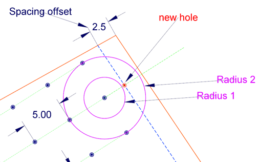
After designing a drillhole pattern, an engineer will typically look for empty regions near the corners and ends of the pattern, where the nearest hole may not provide enough energy to break the rock. For example, the hole spacing is 5 metres, the Spacing Offset Distance is 2 metres and the distance between the last hole in a row and the bounding polygon is 4.85 metres. In this case, an infill hole is added.
Minimum and Maximum Distance
If specified, Minimum distance and Maximum distance values are used as the radii of two circles drawn around the first and last holes. If an adjacent hole is not detected within the radii, then an infill hole is added to the start/end of the row, taking into account the Spacing, the Spacing offset (if any) and the Minimum Distance to Boundary (if any).
Preview
Click the Preview button to see a preview of the extents of the blast pattern and the collars and traces of the pattern.
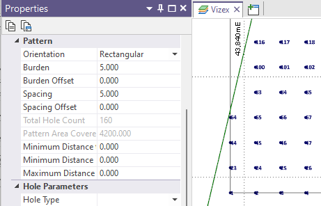
Properties
When you create a pattern, a pattern object is created. When the pattern object is selected its properties can be edited in the Properties window in a Pattern group. This makes it possible to adjust the boundary of the pattern directly or expand the boundary, for example, by changing the Row Count in the Hole Parameters > Holes on first rows group.
Note that the pattern object is only visible when you click inside its corresponding block or the rows or holes inside that block. Double-click the pattern to select it in order to view its properties:
OK
Finally, click OK to create the blast pattern.