Pattern by Polygon
![]()
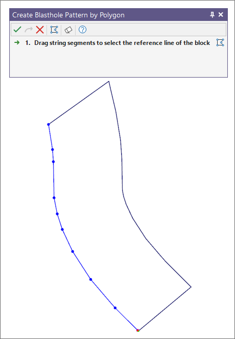
Before using the tool ensure that the block polygon you wish to create the pattern for is loaded and visible in Vizex. When you click on the tool on the ribbon, the Selection Assistant will prompt you to select the reference line of the block. The function will mimic the profile of the selected reference line selection to generate blasthole rows.
Use the mouse to select the string segments that make up the reference line for the block:
Alternatively, you can Digitise the required object/s using the button in the Selection Assistant toolbar. The Selection Assistant will close, providing access to the tools used to create the object.
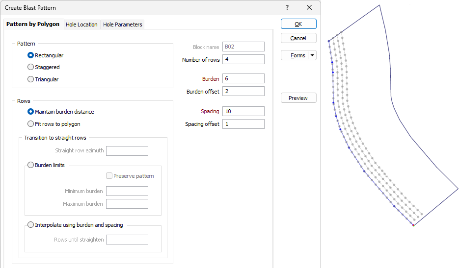
Click on the Selection Assistant’s Accept Selection button to accept the selection once the segments making up the reference line are digitised and/or selected. The Pattern by Polygon tab of the Create Blast Pattern form is displayed:
Pattern
Choose whether the blasthole spacing is Rectangular, Triangular, or Staggered. See: Patterns for more information on the different pattern configurations.
Block name
A unique identifying name for the pattern block will be assigned by the application.
Number of rows
Use this field when you want the tool to create a specific number of rows, rather than create rows to occupy to the entire polygon. This option is ideal for the creation of batter and buffer holes in trim shots, for example.
Burden
Specify the desired distance between blasthole rows.
Burden offset
When an offset is specified, the function will create a gap between the edge of the polygon (which is based on the reference line) and the adjacent blasthole row.
Spacing
Specify the desired spacing between the blastholes on a row.
Spacing offset
When an offset is specified, the function will use the origin and the end point of the reference line to create gaps between the ends of the polygon and the adjacent blasthole.
Note that burden and spacing distance values cannot be negative or zero values. See: Burden and Spacing
Rows
The way in which the rows of the blasthole pattern are generated within the bounds of the polygon will depend on the selected method:
Maintain burden distance
The rows generated by this method mirror the profile on the selected reference line. This method aims to respect the burden distance as rows are fitted within the blast polygon. The specified spacing will also be respected or interpolated where required to produce a practical result.
This method could be used to generate a pattern within trim shot blast polygons.


Fit rows to polygon
This method considers both the front and back of the blast polygon. In other words, the profile of both the selected reference line and back of the blast polygon are used to generate the rows.
This method also ensures that the specified spacing distance between holes on a given row is respected as rows are fitted within the blast polygon. To produce a practical result, the algorithm will interpolate the specified burden where required - for example, when the polygon consists of sharp vertices or tighter sections. However, the specified burden will typically be respected. Burden and Spacing Offsets will also be respected accurately.


Transition to straight rows
The methods within the Transition to straight rows group can be used when you want the pattern to gradually become straight as the rows get further away from the selected reference line.
Straight row azimuth
This value will determine the orientation of the straightened rows. Note: For the best results, you should use an azimuth that is close to the azimuth of the reference line.
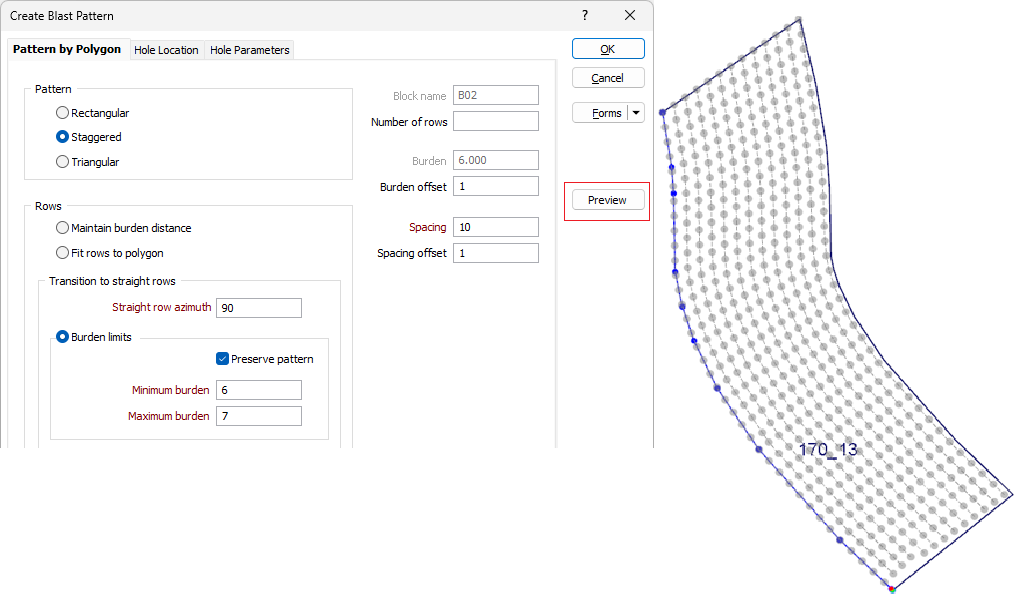
Burden Limits
This method begins by generating rows that mirror the profile of the reference line. Rows further away from the reference line will gradually straighten until completely straight rows are created towards the back of the blast polygon.
Preserve pattern
When this option is enabled, the function will prioritise the preservation of the pattern layout - i.e. Rectangular, Staggered, Triangular. This option may be useful when a design within irregular polygons consists of sharp vertices created by curves or bends. A side effect of this approach is that the specified spacing may not be respected (distance between holes may be higher than specific value) in certain regions of the pattern.
Minimum and Maximum burden
Specify acceptable minimum and maximum burden values for the pattern. The distance between neighbouring rows will remain within these specified limits as the function gradually straightens rows.


Interpolate using burden and spacing
The function interpolates the specified burden and spacing to gradually straighten rows until they become completely straight after a given number of rows. Unlike the other methods, the rows produced by this method do not rely on the profile of the reference line. As such, this method does a superior job of respecting the integrity of the chosen pattern layout.


Rows until straighten
Enter the number of rows to be interpolated until rows become completely straight.
Preview
Click the Preview button to see a preview of the blast pattern and the holes. If you are happy with the result, click OK. Otherwise adjust the parameters you have entered and click on the Preview button to see an updated preview.
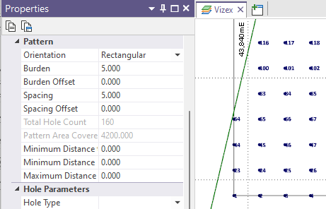
Properties
When you create a pattern, a pattern object is created. When the pattern object is selected its properties can be edited in the Properties window in a Pattern group. This makes it possible to adjust the boundary of the pattern directly or expand the boundary, for example, by changing the Row Count in the Hole Parameters > Holes on first rows group.
Note that the pattern object is only visible when you click inside its corresponding block or the rows or holes inside that block. Double-click the pattern to select it in order to view its properties:
OK
Finally, click OK to create the blast pattern.