Mine Design
This
Improved Variable Constraints
The Variable Constraints tool on the Mining | Pit Design (Dynamic) tab, in the Setup group has been redesigned to provide greater flexibility and allow the use of multiple different constraint types at the same time.
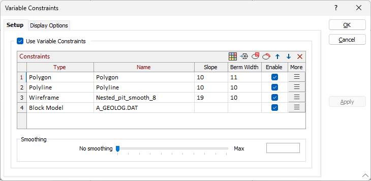
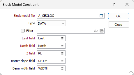
Multiple constraints of various types can be added using the Block Model, Wireframe, Polygon and Polyline buttons in the Constraints grid toolbar. For each constraint type, the Slope and Berm Width values can be entered in the grid. The More button for each row will open the associated form for further details to be configured - for example, the Block Model Constraint form:
The display settings for Polygon / Polyline Constraints and the Constraint Zone can be set using the options on the Display Options tab.
For information on adding constraints to the list, see Variable Constraints.
Constraint List
The Constraint List option has been added on the Mining | Pit Design (Dynamic) tab, in the Setup group to open, manage and edit a list of all of the constraints in the design.
Selecting the Constraint List tool opens the Constraint List dialog which lists all of the constraints in the design:
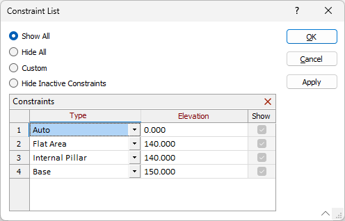
Using the options in the dialog, you can modify the Type and Elevation for each constraint, as well as toggle display settings or Delete a selected constraint/s.
Hide Inactive Constraints
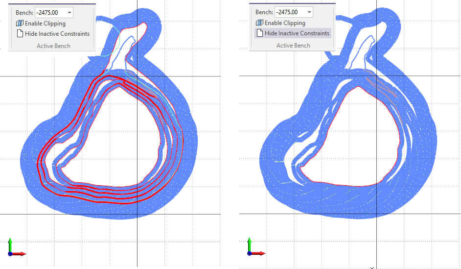
The Hide Inactive Constraints option has been added on the Mining | Pit Design (Dynamic) tab, in the Active Bench group: to hide constraints for benches other than the active (selected) bench.

If an Active Bench is selected from the drop down, setting the Hide Inactive Constraints button ON, will display only constraints for the selected active bench:
Constraint Display Options
Display options for Internal Constraints and External Constraints have been added to the Pit Lines tab of Setup on the Mining | Pit Design (Dynamic) tab, in the Setup group
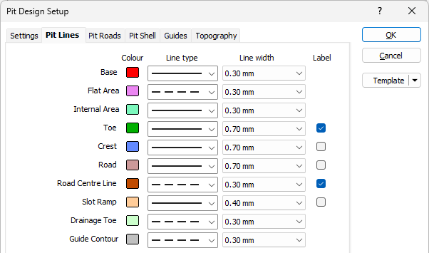
The new options determine the display parameters for Internal and External constraints added to your design.
See Pit Lines for more information.
Polygon and Polyline Constraint Tools
The Variable Constraints Polygon and Select Bench Part tools have been added to Pit Design on the Mining | Pit Design (Dynamic) tab, in the Setup group.
The Polygon Zone tool is used to digitise a new polygon or polyline constraint in your design:

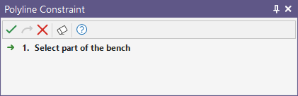
The Polyline tool allows you to select part of a bench to create a polyline constraint.
Road Entry Location
The option to set the road entry location to Inside or Outside of the base (constrained) pit footprint has been added to the Add Road, Edit Road and Road Properties tools in Pit Design (Dynamic).
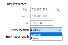
Opting to locate the road entry outside of the base constraint will increase the strip ratio, with extra waste material and no dilution
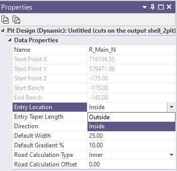
The Entry Location value can be modified in the Road Properties panel:
Bench Properties
The Berm Type and Backslope Gradient values have been added to the Bench details in the Properties pane for Pit Design.
The values can now be viewed and modified from the Properties pane.
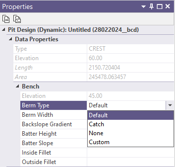
Additionally, support for a Custom Berm Type has been added to allow the setting of the Width of the berm from the default value to a custom solid value. Changing the Width of a berm will automatically set the Berm Type to Custom.
If no value is set for Width, then the Berm Type will be Default and the default width will apply. Setting the Berm Type to Default or Catch will change the Width to the default value.
Berm Taper Options
The Berm Access width and taper length options for road segments in Pit Design have been separated into Toe Access and Crest Access options. These options can be set in the Berm Access section of the Add Road form, as well as the Ramp Segment and Inclined Switchback Segment parameter forms:
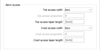
Previously, a single option was available to define the access width and berm taper, applied equally to both sides of the road segment. Separately controlling the values can help reduce dilution and enhance road positioning.
Additionally, the CUSTOM option has been added to both Toe access width and Crest access width to support a custom Toe access and/or Crest access fraction.
Pit Design Minimum Area
The Minimum Area option has been added to the Pit Design Setup form. Setting a Minimum Area value determines the minimum base area that a bench must have before it is created.
Setting a minimum area value can prevent some small benches being generated in areas which are virtually flat.
Improved Pit Design Speed
Optimisations have been added to Pit Design to improve the speed of the finding intersections step of the build for designs where pit strings have a lot of vertices.
The application will pre-calculate the segment lengths to avoid duplication of processes and avoid the more lengthy line intersection calculations when segment bounding boxes do not overlap.
Testing has shown an approximate 50% increase in speed - with the time spent finding intersections dropping from >50% of the total time to < 4%.
For more information on building pit design, see Pit Design (Dynamic).
Pit Design (Dynamic) Interramp Angle
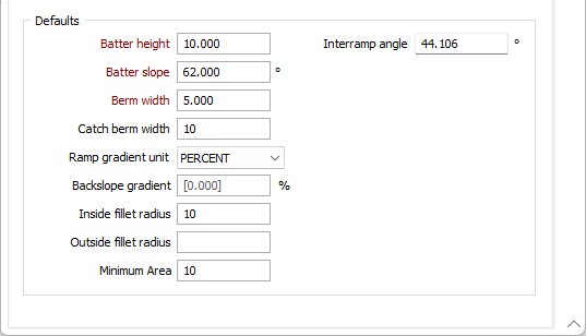
The Interramp Angle field has been added to the Defaults in Settings for Pit Design (Dynamic).
The Interramp angle is the slope angle produced by a number of benches. The value in the field is automatically calculated from the Batter Slope, Batter Height and Berm Width values.
More information on setting up a dynamic pit design is contained in Setup.
Pit Shell (Solid)
The Pit Shell (Solid) option has been added to the Generate Pit Shell tool in Pit Design (Dynamic) on the Mining | Pit Design tab, in the Export group .
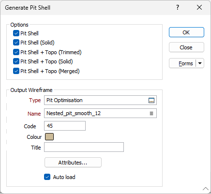
The Pit Shell (Solid) option, when selected, will create the pit shell without clipping to the DTM and close any holes to make the shell solid. This option is particularly useful when exporting an output wireframe to Micromine Alastri.
For more information, see Generate Pit Shell.
Underground Design Workflow
The workflow when creating Vizex String and Underground design layers has been improved to allow the creation of Untitled or new layers.
The Input File can be left blank to create a new Untitled layer with default names for the East, North, Z and Join fields. If you enter a name for the input file that does not exist, you will be prompted to create the file:
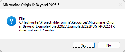
The names of the structural fields North, East, RL, String, Join, Link, and Colour can be entered manually for the new file to be created.
This improved workflow is also supported when creating String layers.