Variable Constraints
On the Mining | Pit Design (Dynamic) tab, in the Setup group Click Variable Constraints to enable and configure variable constraints for your pit design using block models, wireframes and polygons.
![]()
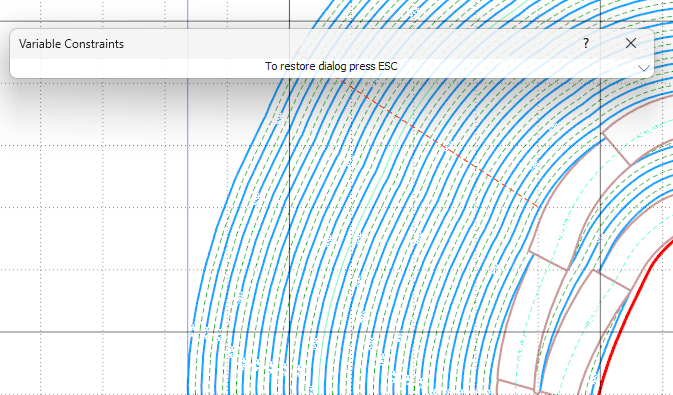
The Variable Constraints form will open, with any constraints applied to the design listed in the Constraints grid:
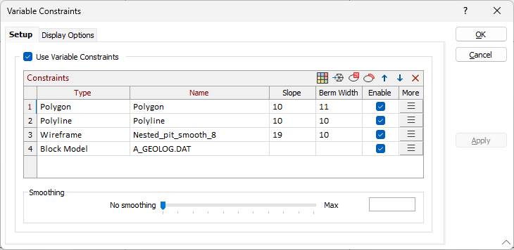
Select the Use Variable Constraints option to apply variable constraints to the pit design. Buttons in the Constraints grid toolbar can be used to create a variable constraint using a Block Model, Wireframe or Polygon.
Block Model
If you click the Block Model button in the Constraints grid toolbar, you can select a Block Model file to define a variable constraint for the pit design.
![]()
The Block Model Constraint form opens:
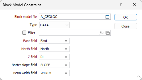
Block model file
Select the appropriate file Type and then double-click (or click on the Select icon) to select a Block Model file that will be used to define variable constraints. If you want to filter the input, select the Filter check box and right-click in the adjacent box to select an existing filter form set or create a new one using the Expression Editor by clicking the icon.
East, North and Z fields
Double-click to specify the names of the Easting, Northing, and Z coordinate fields in the file.
Batter slope and Berm width fields
Optionally, double-click to specify the names of the fields containing the values that will be used for the (Batter slope and Berm width). If either of these fields is blank, the Batter slope / Berm width values will be taken from the Bench level. If the Bench level for either field is also blank, the values will be taken from the defaults on the Input Data tab of the Input Data form.
The defined values for the block model constraint can be modified directly in the fields of the Constraints grid list, or using the Block Model Constraint form by clicking the More button in the grid.
Wireframe
If you click the Wireframe button in the Constraints grid toolbar, you can select a Wireframe file to use for the variable constraint.
![]()
The Wireframe Constraint form opens:
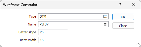
Use the fields provided to select the Type and Name of the wireframe.
Enter the Batter Slope and Berm width values to be applied to the constraint.
The wireframe must be solid and must be unique in the Variable Constraints list. You cannot use the same wireframe more than once and apply different parameters. A warning message will be displayed if any wireframes intersect. If an area of the pit belongs in more than one wireframe, the top-down order of the wireframes in the list will be used to assign priority.
The defined values for the wireframe constraint can be modified directly in the fields of the Constraints grid list, or using the Wireframe Constraint form by clicking the More button in the grid.
Polygon
If you click the Polygon button in the Constraints grid toolbar, you can interactively create a polygon to define the constraint.
![]()
You can digitise a polygon by clicking on each point with the mouse. The length, azimuth, inclination and gradient % of the string is shown on the status bar as a reference. If you hover on a point while digitising, information on the point will be displayed in a pop up:
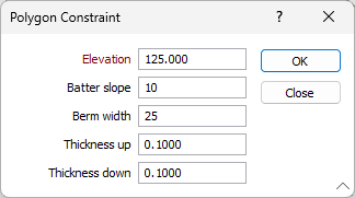
To finish the polygon, either double-click as you digitise the last point or right-click (Esc). The polygon you created will be listed in the Constraints grid as a constraint. You can modify the values of the polygon by clicking the More button to open the Polygon Constraint form:
Polyline
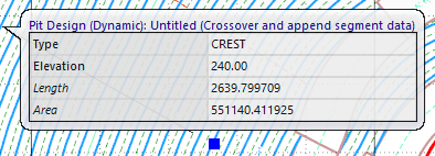
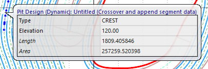
The Polyline button in the Constraints grid toolbar is used to select part of a bench polyline to use as a constraint.
![]()
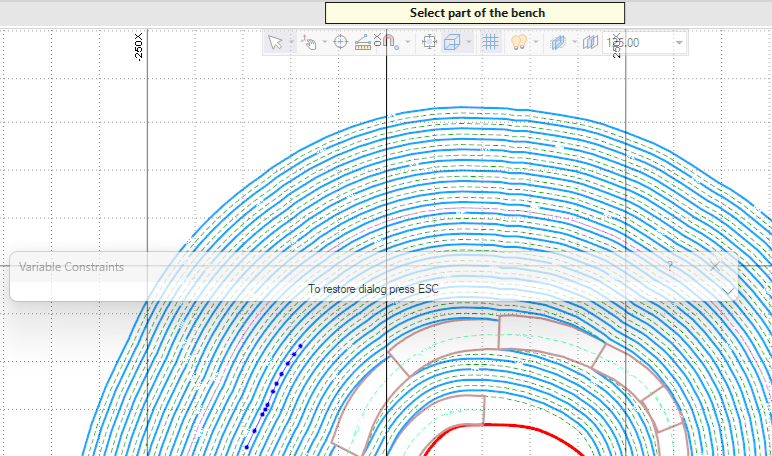
You can select part of the bench by dragging the mouse. The Type, Elevation, Length and Area values for the selection are shown in a pop up if you hover on a point while digitising:
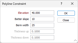
To finish the polyline, either double-click as you digitise the last point or right-click (Esc). The polyline you created will be listed in the Constraints grid. You can modify the values of the polyline by clicking the More button to open the Polyline Constraint form:
Block Model, Wireframe, Polygon and Polygon Part constraints can be removed from the Constraints list or reordered using the buttons in the toolbar to Manage the rows in the list.
Enable
Select the Enable option to set the variable constraint as enabled. This option is ON by default. You can make the constraint inactive by deselecting the option.
Smoothing
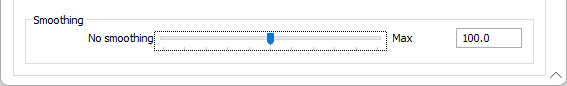
Use the Smoothing slider to set a value by which to smooth the constraints to ensure a smoother transition for the projection.
The smooth constraints process applies a smoothing algorithm to the Variable Constraints process after the initial algorithm and attempts to prevent any sharp bends at the transition between zones.
Slide all the way to the left for no smoothing and all the way right for maximum smoothing. Alternately, enter a value between 0 (No smoothing) and 200 (Maximum) in the field at the right.
The display settings for Polygon / Polyline Constraints and the Constraint Zone can be configured on the Display Options tab.