Grid to DTM
![]()
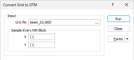
An option to sub-sample the grid before conversion is provided. This allows the 1, 2, 3, 4, 5th, etc point to be used.
Input
On the Input tab of the Grid to DTM form, double-click (F3) to select the name of the Grid file that will be converted to a DTM.
Sample every nth block
To sub-sample the grid before conversion, define the number of X and Y cells that will be used to create the X and Y range of the triangulated surface. Increasing the sampling interval will reduce the amount of memory required to generate a DTM. However, a simpler DTM will be produced as a result.
Output
Type
Select an output wireframe type. DTM is the default output type for this process.
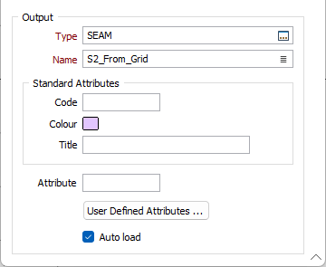
Name
Enter (or click on the Select icon to select) the name of the DTM to be created.
Code
Optionally enter a code that can be used to differentiate between the different outputs generated as a result of the process.
Colour
Optionally double click (F3) to select a default display colour for the output DTM.
Title
Optionally enter a Title that is descriptive of the generated output.
Attributes
Click the Attributes button to set attributes for the DTM output.
User Defined Attributes may be mapped against the fields in the Input file. It is also possible to specify a default value for each attribute. Default values are used when a corresponding value in the Input file is either missing or is not mapped.
Auto load
Select this option to load the generated DTM in Vizex. The default draw style for an auto-loaded wireframe is 3D Shaded.
Run
Finally, click Run to generate the Output DTM.