Output
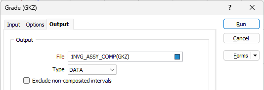
On the Output tab of the Grade Compositing (GKZ) form, specify an output file and the data that will be written to the file.
Output
File
Select a file type and double-click (or click on the Select icon) to select the name of the output file.
Exclude non-composited intervals
Select this option to only write intervals that are included in the compositing process to the output file.
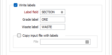
Write labels
Select this option to write labels to the Output file. Composited grade and waste intervals can be labelled.
Label field
By entering the name of a Label field and by specifying waste and grade labels, you can flag waste and grade composites. This field will be created when you run the function and the waste and grade labels will be written to each interval according to its contents.
Enter the name of the field to which the composited grade and waste labels will be written.
Grade label
Enter the code that will be written to the nominated ID field in the output file whenever the interval is a grade composite.
Waste label
Enter the code that will be written to the nominated ID field in the output file for intervals that are not grade composites. Nothing will be written to this field unless the Composite waste intervals option has been selected on the Options tab of the form.
Copy input file with labels
Select this option to copy the Input file and write labels to that file. Enter the name of the file that will be a copy of the Input file plus an additional Label field.
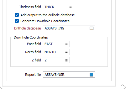
Thickness field
If you have specified a Thickness field on the Input tab, the function will calculate and enter the downhole length of each continuous interval in this field.
Add output to the drillhole database
Select this option to automatically add the composited output file to the drillhole database specified below.
In many cases, it may be useful to store the results of the compositing process to the database that the input interval or assay file is associated with. This aids in visualisation, making it easier to display related downhole data in Vizex.
Generate Downhole Coordinates
Select this option to define trace coordinates and write those coordinates to the specified drillhole database.
Specify a value for the East field, North field and Z field options or accept the [Auto] defaults to auto-generate the field names.
3D coordinates are needed whenever an Interval file is used in a process where the locations of the intervals must be known, for example, resource estimation assignments using polygons.
Drillhole Database
Double-click (or click on the Select icon) to select from a list of drillhole databases in the current project.
Press F5 to create a new drillhole database. Press F4 to edit a drillhole database you have selected.
Report file
Double-click (or click on the Select icon) to select the name of a Report file. If any errors occur during the process, they will be written to the Report file. See: Errors in the Compositing process