Animation
The Source and Destination Solids you specify on the Animation tab of the Settings window will determine what is displayed on-screen during a simulation. Which Settings are available will depend on which simulations are enabled on the General tab.
Source/Destination Solid Tooltips
The Solid Tooltips & Equipment Labels on the Animation tab of the Scenario Settings window, allow you to use Expressions to add more information to the Animation Window.
Tooltips shown in the Animation Window are somewhat separate from tootips shown in the Design Window. When you create tooltips for the Animation Window and the Design Window, the Expression Editor will allow access to different things: Scenario information for Animation and Layer information for Design.
Animation tooltips deal with Source solids and Destination solids and are used to identify Source and Destination locations in your Scenario.
When you hover on a Solid, the Solid Tooltip will show additional text such as qualities, so your tooltip might be:
If(Process=ProcessCoal,
"Coal Ash: " + GetText(SourceImportedCoalFreshASH) + NewLine +
"Coal Sulphur: " + GetText(SourceImportedCoalFreshSulphur),
"")
Source/Destination Equipment Labels
A Source Equipment Label, for example, might include the block location so that it's more clear in images:
Text(SourceStrip) + "/" + Text("SourceBlock")
Note that whatever the Expression, it needs to amount to a String so the Text() function will likely be used.
Source Solids
Set the properties of your Source Solids.
Solid Colours
Click on the drop-down to set standard or custom colours for your Solids. Click on the ellipsis to create a Custom Colour Set. For more information, see: Solid Colours
Solid Depletion Mode
Choose a Solid Depletion Mode:
| Normal | Solids are depleted by the Initial Percentage Completed at the Schedule Start Date. |
| Ignore Initial State | Solids are always full at the Schedule Start Date. |
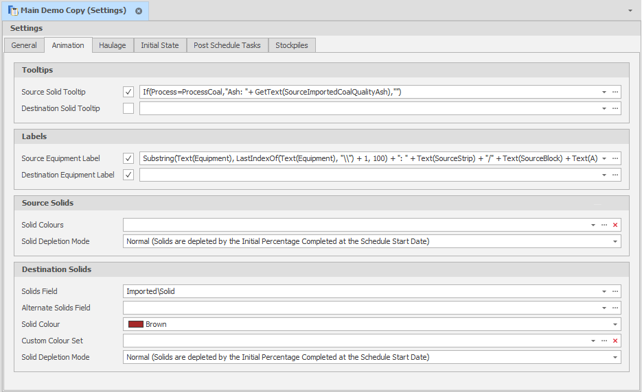
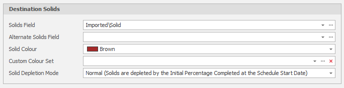
Destination Solids
Set the properties of your Destination Solids.
Solids Field
Link to a Solid Field type. Any Leaf that can be worked (has a Source Quantity greater than zero) can also be displayed visually through the use of 3D Solids by assigning a Solids Field to the process. This means that Leaves that cannot be worked (volume <=0) will not be displayed even with an associated Solid. Any pre-schedule will also apply to the way each Solid is displayed (50% pre-schedule = 50% visible, 100% pre-schedule = 0% visible).
Alternate Solids Field
Link to a Solid Field type. The "Alternate" Solids Field is used when a Solid can't be found in the primary Field (material that may have changed Solid type during reserves processing).
Solid Colour & Custom Colour Set
Click on the drop-down to set standard or custom colours for your Solids. Click on the ellipsis to create a Custom Colour Set. For more information, see: Solid Colours
Solid Depletion Mode
Choose a Solid Depletion Mode:
| Normal | Solids are depleted by the Initial Percentage Completed at the Schedule Start Date. |
| Ignore Initial State | Solids are always full at the Schedule Start Date. |