Haulage Logic
(This Setup step is unavailable unless Haulage is enabled in Settings | General > Simulations.)
![]()
Haulage Logic allows you to group various Output Schedule Steps that have a similar location or haulage strategy. For each Rule that you create in the Haulage Logic window of the application, you use a filter in a similar way to Destination Paths. This filters the Output Schedule and will apply the rule to relevant Output Schedule Steps. Contrary to Destination Paths, the Ranges don't have a default and will need to be set for each Rule. In addition to filters, in the Rule Setup you can control whether or not the Rule is a Network Rule.
The additional filter available (Destination Range) has an extra concept to be aware of, which is "Blanks". Output Schedule Steps that don't have a Destination Leaf are considered to have a Blank Destination Range. The most common use of Blanks is for Processes that don't get Destination Scheduled (Coal, Ore etc) but still need Haulage Simulation.
When running the Scenario, all successful Haul Profiles are generated (the position of each point along the profile) but for each Output Schedule line, only the Haul Profile that meets the Shortest Profile Selection criteria is Simulated (travel times for each Truck). The Shortest Profile Selection setting is available under the Scenario Settings -> Haulage tab.
In order to simulate haulage, you need a path for the Truck to travel down, which in the application is a combination of various Steps. The application provides a wide variety of tools to generate these steps, also known as a Haul Profile. There are two main categories of those tools, Points and Vectors.
Points can either be static (permanent, unchanging such as a defined latitude and longitude) or dynamic (position changes depending on the Schedule Step involved). No matter the kind of Point used, you can consider it to be known. You "know" where the top of a permanent ramp is (static), but you also know for each Schedule Step where the Source Equipment is (dynamic).
The absolute simplest path that can be created in the application involves the use of Static Points, but it is also the most time consuming and least representative. You can immediately add more realism to a set of Static Points by making the Start (Source) and End (Destination) Dynamic Points.
The first problem you'll run into with a Points only method is that you'll be repeating your work over and over again, especially when it comes to roads. Haulage Network (Attach and Detach) Rules are designed to take repetition out of a large portion of your haulage work, as well as allow you to split your workload between Source and Destination.
Points
Points can either be static (permanent, unchanging such as a defined latitude, longitude and elevation) or dynamic (position changes depending on the Schedule Step involved). The Point Sources available are:
-
Entered: A static Point such as the top of a ramp that doesn't move.
-
Source/Destination Node: Refers to a Point3D Centroid type field from the Source or Destination Table. Using the Centroid Field instead is normally recommended (see below)
-
Process/Destination Centroid Field: Similar to the Source/Destination Node but refers directly to the Scenario and Process Settings. Recommend normally as it allows distinction between centroids for different Processes and can be less effort to set up.
-
Previous Step: Can only refer to steps above this one. See Add to Profile below for more description about calculation of Steps and order.
Point Data
The Point Data setting allows you to choose which 3D elements of the Point to use. Although the default uses all three (XYZ) you can also choose to use the elevation only (Z) or the plan view lat/long (XY) only. Any 3D data excluded by this is taken from the previous Step.
Vectors
A Vector starts at the step beforehand and has direction and magnitutde. The direction is set by the Type and the magnitutde is set by the Intersection.
Bearing & Grade: The most common Vector Type, uses a Bearing (XY) and Grade (Z) to set direction.
Coordinates: Creates a direction based on a relative change to the X, Y and Z coordinates. For example the default (0,0,1) creates a Vector that heads directly up.
Towards Point: Creates a direction based on a second point which has all of the options of a normal Point Step. Note that this sets the direction but not the Intersection.
Towards Point with Specified Grade: Similar to Towards Point except it uses a set Grade instead of the Grade between the two.
Haul Profile Segment
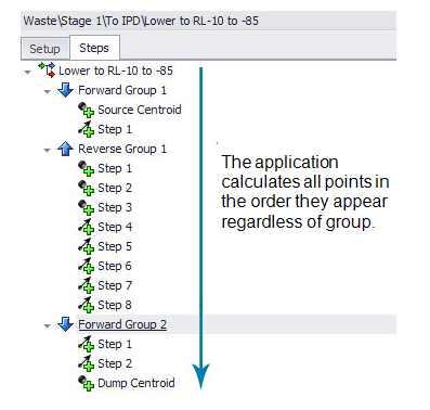
There are two distinct stages that the application goes through when calculating Haul Profiles. The first stage calculates all of the points in space from top to bottom.
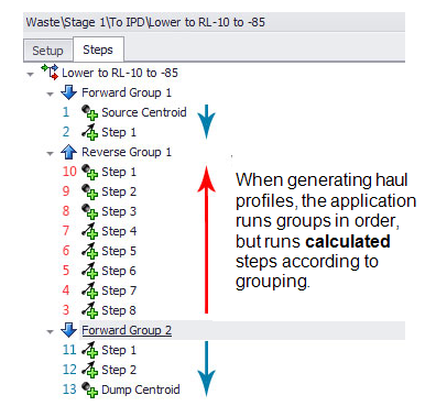
The second stage generates the Haul Profile that the trucks will drive over. This stage uses only steps that are set as "Add to Profile" and moves through each group one at a time in the order set as either Forward (drive top to bottom) or Reverse (drive from bottom to top).