Wireframe Format
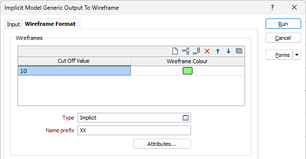
Use the Wireframe Format tab of the Generic Output form to generate wireframe output from an input implicit model file.
Wireframes
To generate wireframe output, use the settings on the Wireframe Format tab.
Cut Off Values and Colours
Use the grid to determine how many Result Wireframes will be output as a result of the process and the Colours to apply to each. You can populate the list by selecting a Numeric colour set from the right-click menu.
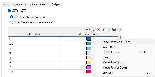
Each cutoff value represents a lower cutoff. Given a value of 0.7, for example, the resultant wireframe will enclose values of 0.7 and higher.
Use the buttons on the local toolbar to Manage the rows in the list.
Type and Name Prefix
Double-click (F3) to select the Type of the output wireframe and specify a Name prefix.
Attributes
(Optional) Click the Attributes button and enter any other attributes for the output wireframes.
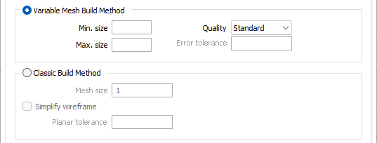
Variable Mesh Build Method
The variable grid marching cube algorithm is a 'primal' marching cube rather than a 'dual' grid marching cube algorithm. In other words it works with true cubes rather than distorted 'dual' cubes.
An advantage of working with true cube is that the cubes are always convex, and hence applying the standard marching cube algorithm will always produce valid wireframes. Dual cubes on the other hand are distorted cubes which can sometimes be concave, leading to possibly invalid wireframes.
One key feature of the variable grid marching cube algorithm is its ability to automatically drill down to smaller grid sizes when encountering thin veins. The standard marching cube algorithm assumes that there is at most once intersection between the iso surface being rendered and each edge of a cube. This assumption does not hold if a vein is thinner than the width of the cube, leading to holes in the resulting wireframes. The variable grid marching cube algorithm handles these by finding as many intersections as possible. If a cube is found to have 2 or more intersects on the same edge, then it must be split up into smaller cubes.
Quality
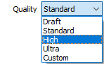
Select a (Draft, Standard, High, Ultra, Custom) output quality option. High maps to the standard quality output, Draft will attempt to create a rougher (but accurate) output more quickly.
Draft mode is expected to be used during the iterative process of fine tuning the modelling parameters so that the result can be previewed more rapidly. Switch to High for final quality iso surface output.
Classic Build Method
With the Classic Build Method radio button selected, you must specify a Mesh size for the wireframe in the field provided.
Simplify Wireframe
Select this option to reduce the number of vertices in the triangulation by eliminating those points that can be removed without causing the triangulation to move by more than the specified tolerance values:
- Planar Tolerance. This is the maximum amount that the triangulation is allowed to move in any direction after vertices are removed.
If no planar tolerance is specified, a default value of 0.01 will be applied automatically. Specifying a large planar tolerance will significantly alter the nature of the triangulation.
Quality
This setting provides a convenient way to control the quality and the speed of wireframe generation. There are five quality settings: Draft, Standard, High, Ultra and Custom.
Setting the quality to Draft allows the general shape of the output wireframes to be generated quickly.
With the exception of Custom, each quality setting has a pre-set error tolerance value. The error tolerance for Draft is approximately twice that for Standard, which, in turn, is twice that for High, etc.
Setting the Quality to Custom allows a user-specified error tolerance. There is no limit to the user-specified error tolerance value (and hence the minimum mesh size), other than that imposed by available system memory.
Build Options
Max triangle Size
To eliminate large meshes, specify a Maximum Triangle Size parameter in grid units.
By default, mesh size is controlled by the tolerance parameter, which specifies the maximum error between the rendered surface and the actual surface. Typically, larger meshes are used where the surface is relatively flat, and smaller meshes are used where the surface has high curvature.
If a Max Triangle Size is specified then all triangles will be that size, or smaller if they fail the tolerance test.
Attributes
Click the Attributes button to set attributes for the wireframe output.
If you want to map user-defined attributes against the fields in an Input file, use the form-based (Wireframe | Create from Strings | Centreline to Solid) function.
Close wireframe at bounding box
Select this option to limit the generated wireframe to the extents of the input data.
Snap wireframe to input data
The generated wireframes may be slightly offset from the points they were created from. Select this check box to snap the wireframes to the input data. Snapping will move the closest triangle to each snap point, if the distance between the two is less than the specified Snap tolerance.
If you do not enter a value, the default tolerance is 1 metre.
Discard volumes less than
If this option is selected, all independent triangle shells with a volume less than the specified minimum volume will be removed.
Any value less than or equal to zero will disable volume removal.
Auto load
Select this option to load the generated output in Vizex. The default draw style for an auto-loaded wireframe is 3D Shaded.
