Points
On the Points tab of the DTM Assign form, you can assign attributes to points that lie above or below the DTM and define the 3D direction that will be used to determine the accuracy of the point assignment. Data outside the chosen assign region can also be deleted.
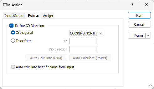
Define 3D Direction
The Define 3D Direction option allow you to choose a non-plan reference plane which will provide better results when assigning
Specify an Orthogonal (LOOKING
WEST, LOOKING NORTH, PLAN) or Transform
reference plane that will determine the direction in which the
Orthogonal
In Orthogonal mode, the Code value prompts on the Assign tab will change to reflect which
For non-orthogonal mode, "above" means above the plane, unless the plane is vertical, in which case "above" is to the north. However, if the plane is a vertical north-south plane, "above" is to the east.
Transform
In Transform mode, Dip and Dip Direction transform parameters are taken from the screen plane orientation (on the 3D View tab of the Display Limits form). Auto Calculate (DTM) will set these parameters to match the mean normal of the surface.
Auto Calculate Points will set these parameters to match the medial axis of the data (or where the silhouette area is minimum).
Auto calculate best fit plane from input
Select this option to calculate the best plane of fit from the input data.
For more information, see: Defining the 3D direction