Defining the 3D direction
During the assign process the normal action is to determine which
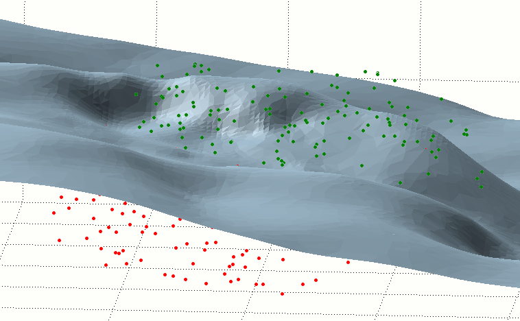
A surface DTM and Point file. The points above are coloured green and those below red.
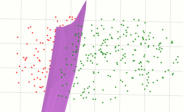
The situation is different when the DTM represents something like a fault. For example, if we want to flag points on either side of the fault, clearly the problem cannot be resolved by the simple above and below method (most of the points would be classified as outside limits). We need to use the same principle, but with a different orientation:
- Rotate the view until all points fall within the silhouette of the fault.
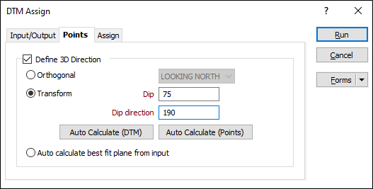
- Determine the orientation of the screen plane (see below). In our example, Dip = 75 and the Dip Direction = 190.
- Use these values in the Grid/DTM | DFT Assign | Assign Points function:
- Run and visually confirm the result.
Calculating the Orientation of the Screen Plane
- Open Display Limits | 3D View (Roll does not matter – can be set to 0)
- Dip = 90 – ABS(Inclination)
- Dip Direction = Azimuth (Inclination +ve) or Azimuth + 180 (Inclination -ve)