Points
If you have chosen to load point features, you can set their display characteristics on the Points tab of the GIS form.
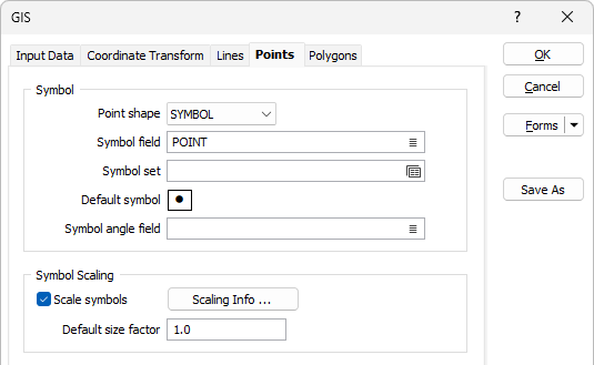
Symbol
Point shape
In the Symbol group, select an option from the Point Shape selection box. Shape options are SYMBOL, CROSS, TRIANGLE, SQUARE and CIRCLE.
Symbol field
Specify the name of
Symbol set
Double click (F3) to select the set that will be used to determine the symbol that will be displayed. The symbol set maps symbols to text strings or numeric ranges. This determines a symbol for each value in the chosen (mapped)
Default Symbol
Double-click in the Default Symbol box to select the symbol to be used when a Symbol
Double-click the Symbol icon to choose a symbol. You can source symbols from any TrueType or OpenType font.
Symbol angle field
Enter the name of the field containing symbol angle values (0-360°). A value of 0 will display the symbol in its natural orientation. A value of 90 will display the symbol rotated 90° in the clockwise direction.
Symbol Scaling
In the Symbol Scaling group, optionally enter a default symbol size factor. Values less than 1.0 will decrease the symbol size and values greater than 1.0 will increase it.
Scale symbols
Optionally select the Scale Symbols option and choose the name of a Scaling field that will control the size of the shapes.
Scaling Info
Optionally, click on the Symbol Scaling Info button to set the scaling method
Default size factor
Enter a multiplier to control the size of the plotted symbol. This must be a value >0.0 and <=10.0. This factor will not change the size of the symbol on the display, however, it will be saved in the plot file. When you create a plot, the symbol will be sized according to your entry.
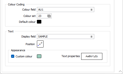
Colour Coding
Colour field
Specify the name of a field which contains the values that will be used to colour-code the display. If you are mapping Colour field values to a Colour Set, the values in the Colour field must be valid RGB, HTML Hex, Hex, or Integer colour definitions.
| Format | Example | |
|---|---|---|
| RGB | 89,169,215 | RGB ordered |
| HTML Hex | #59A9D7 | BGR ordered |
| Hex | 0x59a9d7 | BGR ordered |
| Int | 5876183 | BGR ordered: RED + (GREEN*256) + (BLUE*65536) |
You can choose to select colour values directly from the Colour field without selecting a Colour set. In this case, you can also select a formatted Colour field.
You can view and edit the RGB values assigned to the Colour field in the Property Window. Click on the ellipsis to open the Colour picker:
Colour set
To map values in the Colour field to the colour values in a Colour set, double click (F3) to select the set that will be used to control the display colour. Right-click (F4) to create or edit a Colour set.
Default colour
Double-click (F3) to select the colour that will be used when a Colour field or a Colour set is not defined - or when a value in the Colour field is either not valid or is not mapped in the Colour set.
Text
Display field and font
Specify the name of a Display field containing point annotation values. If you leave Display field empty, only the chosen symbol will be displayed. Select a font to be used to display the text annotation.
If you select a Display field this will override the Use native colour and size information setting on the Input tab.
Position
Position the point annotation. Annotation can be located at one of twelve positions around the point. Double-click (F3) to set the Text Position.
Custom Colour
Double-click the Colour icon (or press F3) to select the colour that will be used to display the labels.
Text Properties
Double-click on the Text Properties Preview box to select a font and set text properties for the labels.