Symbols
Use the Symbols tab to set the position, size and appearance of the symbols (or ticks) that will be used to denote events down the hole.
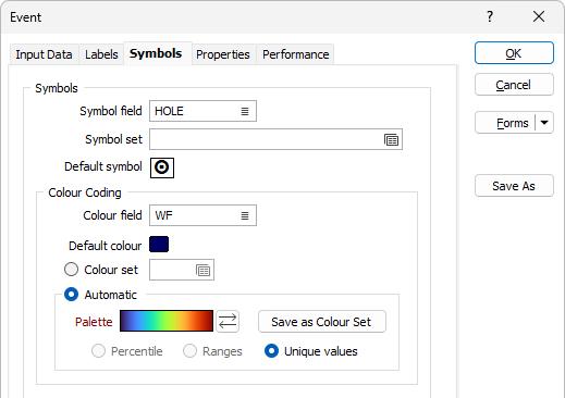
Symbol field
Specify the name of
Symbol set
Double click (F3) to select the set that will be used to determine the symbol that will be displayed. The symbol set maps symbols to text strings or numeric ranges. This determines a symbol for each value in the chosen (mapped)
Default Symbol
Double-click in the Default Symbol box to select the symbol to be used when a Symbol
Double-click the Symbol icon to choose a symbol. You can source symbols from any TrueType or OpenType font.
By default, the symbol will be positioned on the trace. Any offset you enter (see below) will move it away from the trace to the same side as the label. You need to consider the relative positions of the symbol and the label. Incorrect positioning will lead to the symbols obscuring the text of the event labels.
Colour field
Specify the name of a field which contains the values that will be used to colour-code the display.
You can choose to select colour values directly from the Colour field without selecting a Colour set. In this case, the values in the Colour field must be valid RGB, Hex, or Integer colour definitions.
| Format | Example |
|---|---|
| R,G,B | 89,169,215 |
| HTML Hex | #59A9D7 |
| Hex | 0x59a9d7 |
| int | 5876183 |
Default colour
Double-click (F3) to select the colour that will be used when a Colour field or a Colour set is not defined - or when a value in the Colour field is either not valid or is not mapped in the Colour set.
Colour set
To map values in the Colour field to the colour values in a Colour set, double click (F3) to select the set that will be used to control the display colour. Right-click (F4) to create or edit a Colour set.
Automatic
Select Automatic to select a palette and automatically apply colour ranges to the data. The Save As Colour Set button provides the option to save the result as a colour set.
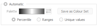
Note that the auto colour set controls are disabled when a Colour field is unspecified:
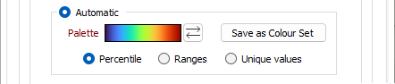
Note: Unique Values is the only supported calculation mode for Event display.
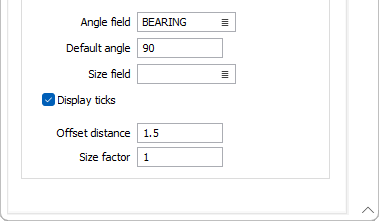
Angle field
Enter the name of the field containing symbol angle values (0-360°). A value of 0 will display the symbol in its natural orientation. A value of 90 will display the symbol rotated 90° in the clockwise direction.
Default angle
Enter the default angle, in degrees, that will be applied to symbols at points where there is no entry in the symbol angle field. The default is 0°.
Size field
Enter the name of the field containing the factor that will be used to control the symbol size. The default is 1.
Display ticks
Select this option to display ticks rather than symbols. The Offset distance and the Size factor you specify are applied to the symbols, or to the ticks (when this check box is selected).
Offset distance (symbols)
Specify an offset distance (in grid units) that will be used to display the symbols/ticks.
Size factor
Enter a size factor for the symbols/ticks. This will be used when there is no entry in the Size field for that point. The default is size factor is 1.0.