Geometric Dependencies
![]()
A Geometric Dependency is used to set dependencies between solids by defining spatial rules: Commonly to define rules between solids that are not on the exact same level or elevation. Geometric dependencies allow you to select which position in the range to connect From and To. A spatial rule can be applied from a first cut, last cut, or all cuts, to the closest, median, furthest, or all intersections. The tool will create a dependency when the rule spatially intersects the predecessor and the successor.
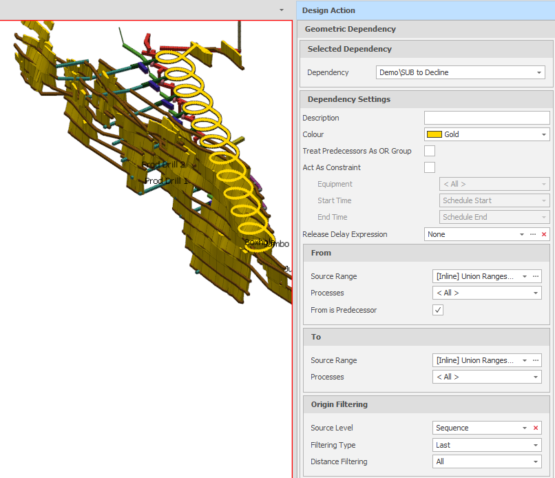
Geometric Dependency Visualisation
You can also add a Geometric Dependency when you select Dependencies on the Home tab, in the Setup group, prior to visualising them in the Animation Window.
Selected Dependency
Select an existing Geometric Dependency. You can right-click in the Dependency Selection pane to Insert Copy, Rename or Delete a dependency.
Create New
Alternatively, right-click and select Add to create a new Geometric Dependency from scratch:
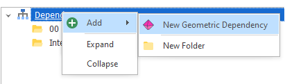
The Geometric Dependency that you Name here is added to the root Dependencies folder (or a sub folder if you specify one).
Dependency Settings
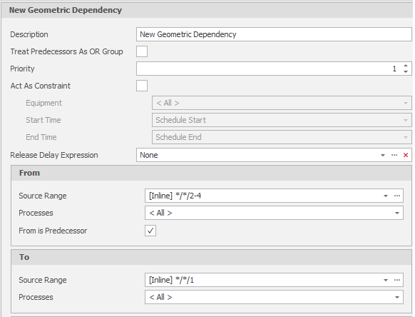
When you add or edit a Dependency of this type, you can set the following parameters (or accept the defaults where applicable):
Description
Optionally, enter a Description that can be used with the Name to further identify the Dependency. Detail useful for diagnosing issues with Dependencies should be added here.
Colour
Use the drop-down to differentiate this type of dependency by colour in the Animation Window.
Treat Predecessors as OR Group
Where multiple predecessor tasks have the same successor task and the OR check box is NOT enabled, the successor task will only be released after ALL of the predecessor tasks are completed.
Where multiple predecessor tasks have the same successor task and the OR check box is enabled, then the successor task will be released when ANY of the predecessor tasks are completed.
Act As Constraint
Normally a Dependency takes into consideration the relationship between Tasks regardless of the Equipment or Date involved. Selecting the Act As Constraint check box
For example, if the user ticks act as constraint in the dependency range, and excludes Drills, the Drills will not honour the dependency range.
Release Delay Expression
The key terminology to be aware of is Released (no Dependency on this Task) and Unreleased (Waiting on Dependency). This will become useful in the Snapshot Viewer and how it can help diagnose issues with Source Paths and Dependencies.
Once a Predecessor Range has been completed, the Release Delay controls how long until the Successor Range is considered "Released" and can be worked. Accept the default (None) or build a Release Delay Expression using the operators, constants and functions provided by the Expression Editor.
From
Specify a Source Range/Destination Range which defines the Tasks "from which" search cones are drawn at their centroids in order to determine the Tasks "to which" dependencies will be made. e.g.
[INLINE] */*/2-4
Destination Range is only visible if Destination scheduling is enabled in Settings > Simulations.
Processes
Allows you to control which Processes are used for the Dependency.
From is Predecessor
This check box is selected by default and means that dependencies are linked from each FROM task to the specified TO tasks.
If this check box is NOT selected, the reverse is true (dependencies are linked from each TO task to the specified FROM tasks).
To
Specify a Source Range which defines the "To" tasks that are allowed to be included in the search results of the specified "From" tasks. e.g.
[INLINE] */*/1
Processes
Allows you to control which Processes are used for the Dependency.
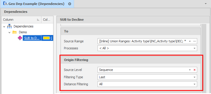
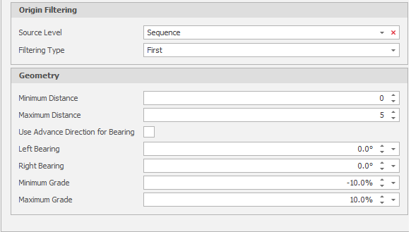
Origin Filtering
Optionally, set a filter to limit the search by making the origin of the FROM tasks the first/last node of the specified level.
Source Level/ Destination Level
Select the level to filter on in the Source table/Destination table (defaults to the lowest "LAST" level)
Filtering type
Destination Level is only visible if Destination scheduling is enabled in Settings > Simulations.
Select a (First, Last, All) filtering type:
-
First is the highest in the node structure for that level.
-
Last is the lowest in the node structure for that level (this is the default setting).
-
All nodes (no filtering).
Distance Filtering
Select an (All, Closest, Furthest) Distance Filtering option. Defaults to All but allows links to be excluded by only considering the closest or furthest connections.
Geometry
Min Distance
Set the minimum distance the solid has to be away from the search point (this affects the shape of the search cone).
Max Distance
Set the maximum distance the solid has to be away from the search point (this affects the shape of the search cone).
Use Advance Direction for Bearing
If this check box is selected, the 0 degrees bearing is the advance direction, otherwise the 0 degrees bearing is North.
Left Bearing
Specify how far left of 0 degrees the solid can be (this affects the shape of the search cone)
Right Bearing
Specify how far right of 0 degrees the solid can be (this affects the shape of the search cone)
Minimum Grade
Specify how low the search solid can be relative to the search point (this affects the shape of the search cone).
Maximum Grade
Specify how high the search solid can be relative to the search point (this affects the shape of the search cone).
Visualisation
Select a (Select from Solids, All Solids) Visualisation Mode:
-
Select from Solids: You will be prompted to select solids to preview the Geometric dependency settings you have set.
-
All Solids: All solids will be included in a preview of the Geometric dependency settings you have set.
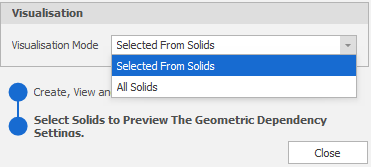
Close
Click Close to close the Design Action pane.