Setup Stratigraphies
![]()
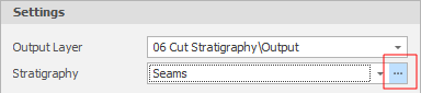
You can also open the Stratigraphies Window when you click on the ellipsis to the right of the Stratigraphy Setting in the Cut Stratigraphy dialog:
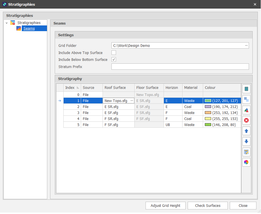
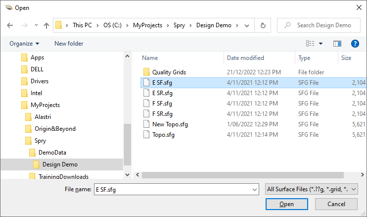
In the following example, E SR, E SF, F SR and F SF are Grid files which represent the Roof and Floor of the seams that run through a pit. The layering of those seams and the materials they contain have been defined.
A read-only "Floor File" column, which pairs each Roof with its Floor, is provided for visualisation purposes only.
Add
To add a Stratigraphy:
-
Right-click on the Stratigraphies node of the selection tree and select New Stratigraphy.
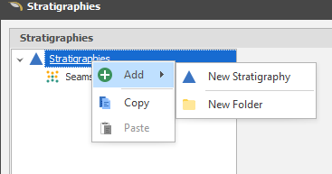
New Folder
You can group stratigraphies by adding them to folders.
Settings
When you have created a Stratigraphy or opened a Stratigraphy for editing, the following settings must be defined:
Grid Folder
When adding horizons from external grid files (see Source = File below), click on the ellipsis to navigate to the location of a default folder.
Include Above Top Surface
Select this check box to include overburden that lies above the top surface.
Include Below Bottom Surface
Select this check box to include underburden that lies below the bottom surface.
Stratum Prefix
When adding horizons from external grid files (see Source = File below), as a general naming convention, Roof and Floor grid names are given a prefix which identifies all of the seams in a particular mine. For example, MACBOW.sfg is a Base of weathering (BOW) floor seam at the MAC mine.
If you have two grids named BOW and MACBOW and the specified Stratum Prefix is MAC, BOW would appear twice in the list of grids. For this reason, where a surface grid name does NOT include the prefix, quotes are used to enclose the name, making it clear that this is the literal name of that grid, rather than the prefix-excluded name.
Horizon
Typically, the name of each Coal or Waste seam.
Material
The name of the material. Typically, whether the seam is a Coal seam or a Waste seam. Material over the top seam and under the bottom seam is typically defined as Overburden (OB) and Underburden (UB).
Colour
For each horizon: Click on the Colour cell to choose between theme colours, standard colours or select a colour from a chosen palette.
Stratigraphy
The input grids are listed in stratigraphic order from highest Z to lowest Z. To change the order or the number of the Horizons and set stratigraphy colours, use the tools provided on the local toolbar.
|
|
Add Files: Add horizons from one or more external grid files. |
|
|
Add Grids: Add horizons from one or more grids stored in the project/model database. See "Source" (below) |
|
|
Add Triangulations: Add horizons from one or more triangulations stored in the project/model database. |
|
|
Delete the row(s) currently selected in the list. |
|
|
Move the currently selected row(s) Up to reorder the list. |
|
|
Move the currently selected row(s) Down to reorder the list. |
|
|
Use the Bulk Editor to make bulk modifications to the list of horizons. |
Click on a Colour box to apply a colour from a theme or assign a custom colour for each horizon. Alternatively:
|
|
Click the Palette icon to apply a Colour Palette to the entire stratigraphy. |
| You can also use the SHIFT key to select multiple horizons, then right-click and select Apply Colour Palette for just the horizons you have selected. |
Source
Choose where the data used to define the stratigraphies is sourced from:
|
Source |
Description |
|---|---|
|
File
|
Navigate to a folder location where one or more external grid files are located. As shown in the example, ideally the names of each file will help to identify a particular horizon:
|
|
Grid |
Choose a folder under the Grids node in the Design Data pane and/or select individual grids. Internal grids may be "project grids" (grids stored in the project/model database) or "reference grids". |
|
|
When you convert a project grid to a reference grid, the grid data is no longer stored in the project/model database. Instead, the grid data is loaded directly from a referenced (*.grd) file. |
|
Triangulation |
Choose a folder under the Triangulations node in the Design Data pane and/or select individual triangulations. |
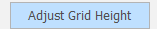
Adjust Grid Height
Click the Adjust Grid Height button to run the Adjust Stratigraphy utility. In this case, a maximum distance between grids check is not applied.
Check Surfaces
Click the Check Surfaces button to verify that the surfaces you have specified exist and are conformant. This is recommended.