Create Triangulation Intersection Outline
![]()
Do the following:
-
Select the Source of the data that will be used as input to the function:
Selection Design elements you have interactively selected in the Design Window. Visible Design elements that are visible in the loaded layer. Elements that have been specifically hidden are excluded. This a quick way of selecting all visible elements in a layer without having to explicitly select them. Layer One or more layers that you select. Names of layers currently loaded in the Design Window are shown in bold. For large datasets, you may prefer to select a layer rather than load that layer and select all of the elements in the layer. Selecting a non-applicable layer will have no effect. In most cases, an error icon
 will indicate the chosen input layer is not valid. Hover over the icon to view a validation hint.
-
Use the drop-down to select an Output Layer.
Tip: In the Layer Selection pane, you can right-click on the Layers node (or a folder) to Add a new layer.
-
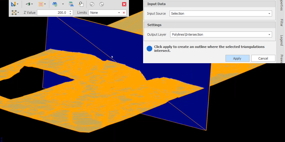
Click Apply. For example, you have a pit solid and want to draw an intersection where a plane cuts through it:
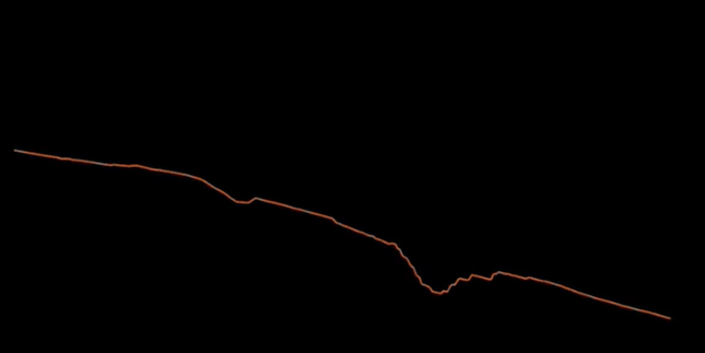
An outline is created where the selected triangulations intersect:
See also: Create Boundary from Plane