Create Boundary from Plane
![]()
There are three modes:
Slope
Create a line with 2 points:
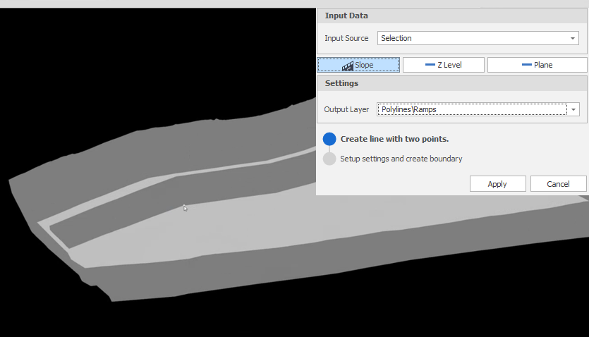
A plane is temporarily created from the digitised line:
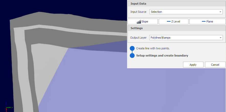
Select the solid you want to intersect with and click Apply:
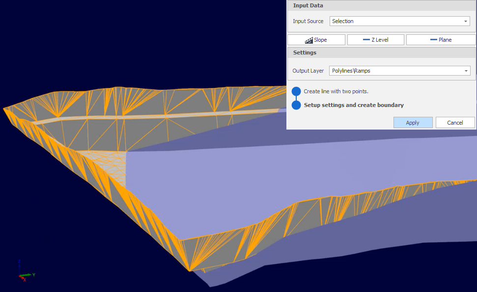
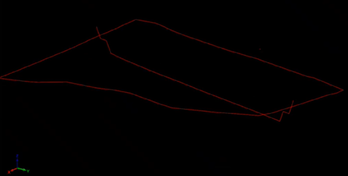
A boundary is generated around the selected solid using the temporary plane:
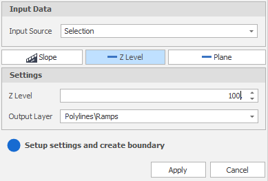
Z Level
Set a specific Z level, for example, 100:
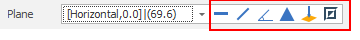
Plane
Use the tools to the right of the Plane drop-down to select a Plane Selection mode and define the plane:
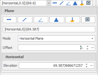
-
Click Horizontal on the plane selection toolbar.
-
Digitise a point to set the elevation of a horizontal plane.
-
(Optional) Use the spin controls or enter a value to Offset the plane along the normal by a set amount. A negative offset value is allowed.
The point you have digitised are used to populate a Text Edit box at the top of the Plane Selection pane.
The Text Edit box can also be used to create or edit a plane from a string. The string format shows the plane selection mode and a zero or non-zero (if specified) offset value, followed by the elevation value.
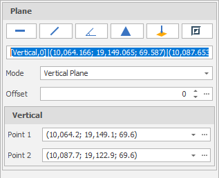
-
Click Vertical on the plane selection toolbar.
-
Digitise two points to define a vertical plane.
-
(Optional) Use the spin controls or enter a value to Offset the plane along the normal by a set amount. A negative offset value is allowed.
The points you have digitised are used to populate a Text Edit box at the top of the Plane Selection pane.
The Text Edit box can also be used to create a plane from a string. The string format shows the plane selection mode and a zero or non-zero (if specified) offset value, followed by the string format used for the conversion, which is “(x, y, z) | <a, b, c>“ where each lettered character can be a decimal number. (x, y, z) refers to the point of the plane. <a, b, c> refers to the vector normal of the plane.
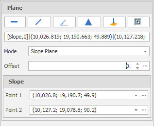
-
Click Slope on the plane selection toolbar.
-
Digitise two points to define a slope plane.
-
(Optional) Use the spin controls or enter a value to Offset the plane along the normal by a set amount. A negative offset value is allowed.
The points you have digitised are used to populate a Text Edit box at the top of the Plane Selection pane.
The Text Edit box can also be used to create a plane from a string. The string format shows the plane selection mode and a zero or non-zero (if specified) offset value, followed by the string format used for the conversion, which is “(x, y, z) | <a, b, c>“ where each lettered character can be a decimal number. (x, y, z) refers to the point of the plane. <a, b, c> refers to the vector normal of the plane.
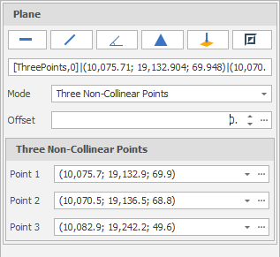
-
Click Three Points on the plane selection toolbar.
-
Digitise three non-collinear points to define a plane.
-
(Optional) Use the spin controls or enter a value to Offset the plane along the normal by a set amount. A negative offset value is allowed.
The points you have digitised are used to populate a Text Edit box at the top of the Plane Selection pane.
The Text Edit box can also be used to create a plane from a string. The string format shows the plane selection mode and a zero or non-zero (if specified) offset value, followed by the string format used for the conversion, which is “(x, y, z) | <a, b, c>“ where each lettered character can be a decimal number. (x, y, z) refers to the point of the plane. <a, b, c> refers to the vector normal of the plane.
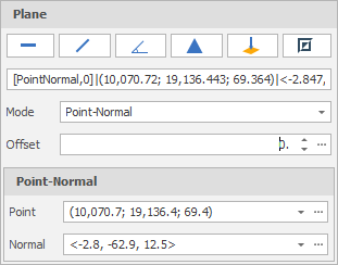
-
Click Point Normal on the plane selection toolbar.
-
Digitise two points that define the origin and the normal of a plane.
-
(Optional) Use the spin controls or enter a value to Offset the plane along the normal by a set amount. A negative offset value is allowed.
The points you have digitised are used to populate a Text Edit box at the top of the Plane Selection pane.
The Text Edit box can also be used to create a plane from a string. The string format shows the plane selection mode and a zero or non-zero (if specified) offset value, followed by the string format used for the conversion, which is “(x, y, z) | <a, b, c>“ where each lettered character can be a decimal number. (x, y, z) refers to the point of the plane. <a, b, c> refers to the vector normal of the plane.
To invert the currently defined plane, click Invert Plane on the plane selection toolbar.
A vertical plane is inverted by swapping the two points and the mode does not change. When a horizonal or slope plane is inverted, the mode changes to Point-Normal. This is because a horizontal or slope plane always has a normal of <0,0,1>. The inverse is a normal of <0,0,-1> and this is only possible with a point normal plane definition.
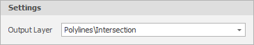
Output Layer
Use the drop-down to select an Output Layer.
Tip: In the Layer Selection pane, you can right-click on the Layers node (or a folder) to Add a new layer.
Apply
Click Apply to create a boundary from the plane.