Slope Restriction Regions
Select the Use Multiple Slope Restriction Regions check box to set the parameters of up to 10 slope restriction regions. You can then choose how the boundaries of the slope restriction regions are defined.
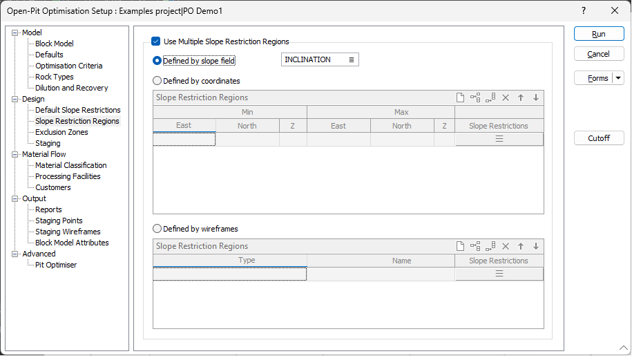
Defined by slope field
This field specifies a field in the block model that contains the slope angles required for each block. The regions are defined as being all of the blocks with similar slope angles.
Defined by coordinates
Select this option to delineate regions for which different stope design parameters apply by specifying ranges of coordinate values.
Min East
(Min/Max coordinates only.) Specify the easting coordinate for the lower extremity of the region.
Min North
(Min/Max coordinates only.) Specify the northing coordinate for the lower extremity of the region.
Min Z
(Min/Max coordinates only.) Specify the elevation (Z) coordinate for the lower extremity of the region.
Max East
(Min/Max coordinates only.) Specify the easting coordinate for the upper extremity of the region.
Max North
(Min/Max coordinates only.) Specify the northing coordinate for the upper extremity of the region.
Max Z
(Min/Max coordinates only.) Specify the elevation (Z) coordinate for the upper extremity of the region.
Slope Restrictions
Select the form set that defines the slope restriction (Bearing and Slope Angle) definitions for each slope restriction region. See: Default Slope Restrictions.
Use the buttons on the local toolbar to Manage the rows in the list.
Defined by wireframes
Wireframe Type/Name
Select a wireframe of a specified Type and Name to define each stope region.
Slope Restrictions
Select the form set that defines the slope restriction (Bearing and Slope Angle) definitions for each slope restriction region. See: Default Slope Restrictions.
Use the buttons on the local toolbar to Manage the rows in the list.