Model
Except for the design parameters, which are different for stopes and pits, the user experience for the Stope Optimiser is very similar to that for the Pit Optimiser – if you can use one, you can use both.
Block Model
On the Setup > Model > Block Model page, specify:
- The name of the file containing the block model for which the optimum stope/pit layout is to be determined.
- The fields from which coordinates, densities, cost adjustment factors and block factors should be obtained.
- Whether the block model is a Full model, which includes all waste and ore for the region of interest, or an Ore body model, which typically contains only the ore component.
- Optional digital terrain model and custom optimisation limits for the ore body model.
- Optional factors to be applied to block sizes in each direction.
- How the optimisation values for the blocks should be derived.
When deciding whether to use a Full model or an Ore body model within the Stope/Pit Optimiser, the following factors should be considered:
| Consideration | Full model | Ore body model |
|---|---|---|
| Missing blocks | Treated as air. | Filled automatically as required with waste blocks assigned properties in accordance with the Mine > Model > Defaults option. |
| Surface DTM | Not supported. Must already be restricted by air. | Supported. Blocks above treated as air. |
| Custom optimisation limits | Not supported - optimisation region defined by extents of block model. Use exclusion zones. | Can be defined by ranges of coordinates. |
| Exclusion zones | Sequenced inclusions/exclusions of wireframes or polygons define optimisation region. | |
| Factor fields | Supported. | Factored ore body models are NOT supported and should not be used. |
| Block model rotations | Azimuth rotations supported. | Azimuth, Dip and Plunge rotations supported. |
| Waste block properties | Can be specified for each block. | Values for all blocks specified by Mine > Model > Defaults option |
| Availability of variable values in expressions | COORD_X, COORD_Y, COORD_Z and <FIELD NAME> available only for blocks that exist in block model. |
|
| Analysis | Fully supported. | Not supported directly – however, Optimisation Database supported. |
Tip: To minimise the potential for arithmetic anomalies caused by material classifications changing between nested stope layouts, it is recommended that Full models with Density field (or Tonnage factor field) specified be used wherever possible. If Density field (or Tonnage factor field) is not specified, or modelled values are not available (as may be the case for Ore body models), the default values for Ore Density and Waste Density specified on the Mine > Model > Defaults tab apply. If these values are significantly different, the change in classification of a block from waste in one nested stope layout to ore in the next nested stope layout may produce a significant change in the masses and element grades reported for that block.
Input
Block model file
Select the file containing the block model for which the optimum design is to be produced.
Sub-blocked models are supported. For the purposes of the optimisation, they will be regularised automatically as required. Results can be reported for either the regularised blocks or the supplied sub-blocks.
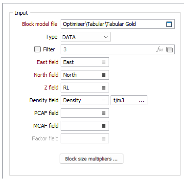
Type
Select the format (DATA / SURVEY / STRING / ODBC LINK / MDB LINK) in which the data for the block model is presented.
East field
Select the field in the block model file from which the easting coordinate for each block should be sourced.
Expressions are not supported for this setting.
North field
Select the field in the block model file from which the northing coordinate for each block should be sourced.
Expressions are not supported for this setting.
Z field
Select the field in the block model file from which the Z (elevation) coordinate for each block should be sourced.
Expressions are not supported for this setting.
Density field
(METRIC projects, optional, recommended.) Select the field in the block model file from which the density for each block should be sourced.
For block dimensions specified in metres (m), densities must be expressed in tonnes per cubic metre (t/m3). Specific gravity values are suitable for this purpose.
Use the Density unit field to select the density or tonnage factor unit, which determines the units used for calculating block mass and volume.
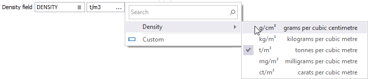
For example if t/m3 is entered, block mass will be treated as tons, volume as cubic meters and block size as meters. Or if ft3/shtn is given, block mass will be in short tons, volume in cubic feet and block size in feet. If there is already a unit on the block model density field then values will be converted from that unit into the selected unit before being used in calculations.
Tonnage factor field
(IMPERIAL projects, optional, recommended.) Select the field in the block model file from which the tonnage factor for each block should be sourced.
Tonnage Factors must be specified in units consistent with those used for specifying the dimensions of the blocks in the model. No additional unit conversions are performed by the Optimiser.
Using 1 foot = 0.3048 metres, 1 pound = 0.45359237 kilograms, and 1 short ton = 2000 pounds, Tonnage Factors expressed in cubic feet per short ton (ft3/sh tn) can be converted to cubic metres per tonne (m3/t) by multiplying by 0.03121398, or to cubic feet per tonne (ft3/t) by multiplying by 1.10231131.
PCAF field
(Optional.) Select the field in the block model file from which the Processing Cost Adjustment Factor (PCAF) for each block should be sourced.
The Processing Cost Adjustment Factor (PCAF) applies to costs that are incurred only if the ore is processed. The factor must be specified relative to the “standard block”, for which it is assumed that PCAF = 1.
If this field is left blank, or values are missing from the specified field, then the Default PCAF value defined in the Model > Defaults tab will be used.
MCAF field
(Optional.) Select the field in the block model file from which the Mining Cost Adjustment Factor (MCAF) for each block should be sourced.
The Mining Cost Adjustment Factor (MCAF) applies to costs that are incurred only if the block is mined – costs that stop when mining stops are not affected. The factor must be specified relative to the “standard block”, for which it is assumed that MCAF = 1.
If this field is left blank, or values are missing from the specified field, then the Default MCAF value defined in the Model > Defaults tab will be used.
The MCAF appropriate to the block’s classification as ore or waste will be applied to each block as required.
Factor field
(Optional.) Select the field in the block model file from which the block factor for each block should be sourced.
This field is disabled when Model Type > Ore body is selected. Ore body models with block factors are not supported and should not be used.
Tip: Block factors can be removed from block models by using Modelling > Block Model Tools > Regularise.
Block Size Multipliers
When deriving optimum stope/pit layouts for large models, particularly in preliminary testing of parameter configurations, it can be beneficial to combine full-size (i.e. not sub-blocked) blocks in one or more directions using block size multipliers. The optimisation will be completed in less time and the results will still be reported at the resolution of the supplied block model – however, the granularity and selectivity of the solution may be impacted.
For more information, see: Block Size Multipliers
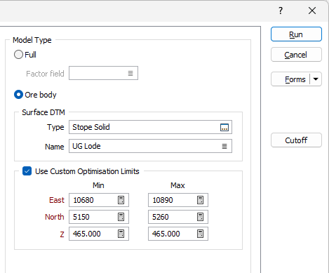
Model Type
Select the type (Full / Ore body) of block model supplied.
Full
Select if Full block model, which includes all waste and ore for the region of interest, is supplied.
Ore body
Select if an Ore body block model, which typically contains only the ore component for the region of interest, is supplied.
| Surface DTM | (Ore body model only.) Specify the digital terrain model (DTM) to be used to model the surface of the region of interest. This can be used to represent the topography or the extent of existing mining. |
| Type | Select the type of digital terrain model to be used to model the surface. |
| Name | Select the name of the digital terrain model of the specified type to be used to model the surface. |
| Use Custom Optimisation Limits | (Ore body only, optional.) Select to define the optimisation region by ranges of coordinates. |
| Min East, Min North, Min Z | Specify the easting, northing and Z coordinates for the lower extremity of the optimisation region. |
| Max East, Max North, Max Z | Specify the easting, northing and Z coordinates for the upper extremity of the optimisation region. |