Generate Tunnels
![]()
In the Workflow Pane, you can also navigate to this function as part of your Scheduling Advance Default Workflow.
Input Source
Select the Source of the data that will be used as input to the function:
| Selection | Design elements you have interactively selected in the Design Window. |
| Visible | Design elements that are visible in the loaded layer. Elements that have been specifically hidden are excluded. This a quick way of selecting all visible elements in a layer without having to explicitly select them. |
| Layer | One or more layers that you select. Names of layers currently loaded in the Design Window are shown in bold. |
For large datasets, you may prefer to select a layer rather than load that layer and select all of the elements in the layer. Selecting a non-applicable layer will have no effect. In most cases, an error icon ![]() will indicate the chosen input layer is not valid. Hover over the icon to view a validation hint.
will indicate the chosen input layer is not valid. Hover over the icon to view a validation hint.
Settings
Output Layer
Use the drop-down to select an Output Layer.
Tip: In the Layer Selection pane, you can right-click on the Layers node (or a folder) to Add a new layer.
Block Model Interrogation
Optionally, select one or more Block Model Interrogations to define what attributes should be populated with the values of a given block model field.
Block Model Interrogations allow you to generate quality values from one or more Block Models and assign aggregated values to fields in the Scheduling Data Table. A pre-requisite is that the quality fields you want to interrogate (Gold Grade and Density, for example) have already been setup in the target Data Table, alongside the calculated fields (Tonnes, Volume and Gold Grams, etc) populated as a result of the interrogation.
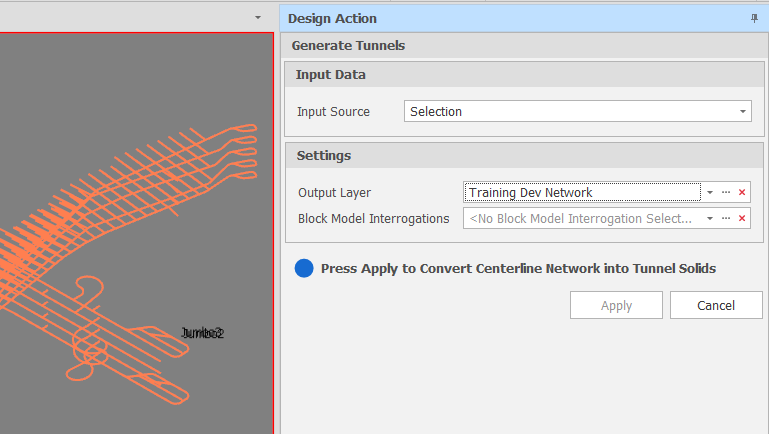
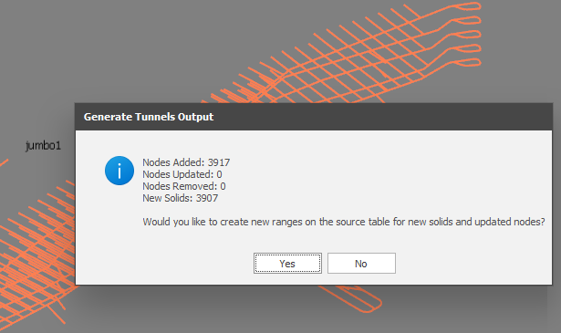
Click Apply to generate tunnel solids from centrelines.
In the Properties pane, the Tunnel Properties > Tunnel property must be assigned to all selected centrelines (or to all centrelines when a Network Layer is the Input Source) otherwise an error message is shown. For more information, See: Tunnels
The results of the process are reported. You are given the option to create or update the ranges on the source table with the solids and nodes you have generated.
On the Design ribbon, in the View group, click Reload Solids to refresh the Animation Window.
Note: If Source Solids are set to hidden, or the Hide Solids button has been pressed, you will not be able to see your solids. For more information, see: Hide/Show Solids