Development Network
A case that has the Data > Development Network option enabled as part of its Scenario Settings is able to support underground mine scheduling and reserving. Inputs to the process are Centreline strings which represent a Development Network and Solids which represent the stopes to be mined. From these, a set of scheduling solids are generated under a "Development Network Layers" node of the Design Data pane.
When you create a new case in the Project Explorer, Development Intersection and Development Sequence dependencies are generated. Sequence dependencies are generated from all internal dependencies in the Development Network Layer, based on their Cut, and are case-specific. Similarly, intersection dependencies are generated from the intersections in the Development Network Layer.
To support the creation of Development Network Layers, a number of options are required to be selected as part of your Scenario Settings.
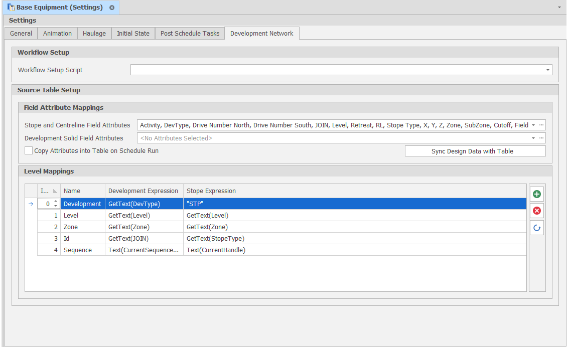
Scenario Settings: Development Network
In the Workflow Pane, you can also navigate to this function as part of your Scheduling Advance Default Workflow.
Source Table Setup
Field Attribute Mappings
Attribute Fields are a special group of fields which are imported into the Data Table. These Attribute Fields are Design Attributes that are imported from Development Network and Stope layers and linked to the Data Table. During the Tunnel and Stope generation processes, Table Solids Fields are populated with the data from the design centrelines and the stope solids. These attributes are essential for building and running the schedule.
Stope & Centreline Field Attributes
Map the Design Attributes of the Development Network and the Stope Layers to the Centreline Field Attributes. These attributes will be synced to the Data Table.
Development Solid Field Attributes
Map the Design Attributes of the Output Triangulation Development Network (created during the Generate Tunnels process) to the Development Solid Field Attributes. These attributes will be synced to the Data Table.
Copy attributes into Table on Schedule Run
Select this check box to delay copying design attributes until the schedule is run.
Click the Sync Design Data with Table to ensure that an update to the Design Data will be reflected in the Data Table and vice versa.
A warning is displayed if attributes fail to sync because of unloaded or deleted data. Note that the design layers need to be loaded before synchronising.
Note: If you remove a Data Table field created as a result of Attribute Field Mapping, that field will be recreated every time the Field Attribute Mappings are synchronized with the Data Table and every time the model is reopened (if the mapping still exists in any scenario).
This is intended behaviour because the Attribute which caused the creation of the field still exists and is still linked in the Field Attribute Mappings. To prevent an Attribute Field from being recreated you must ensure that the attribute of the same name as the field is unticked in the Field Attribute Mappings of every scenario in the project.
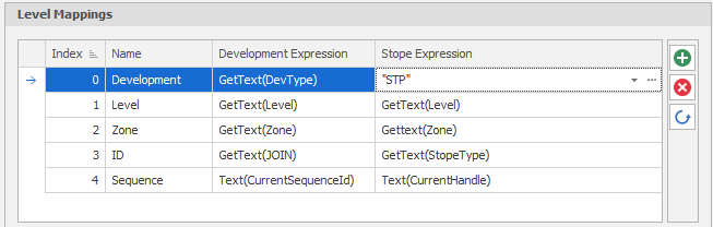
Level Mappings
In Micromine Advance, a Data Table can contain as many Levels as defined by the user. Advance allows for two sets of unique branches to be formed; one for Development and one for Stoping. It is important to note that each will have the same number of Levels. Each Level structure must contain unique full nodes or leaves.
To derive the ranges that will be used for scheduling, Development Expressions and Stope Expressions can be built for the Levels defined as part of the setup of the model.