What’s New
This
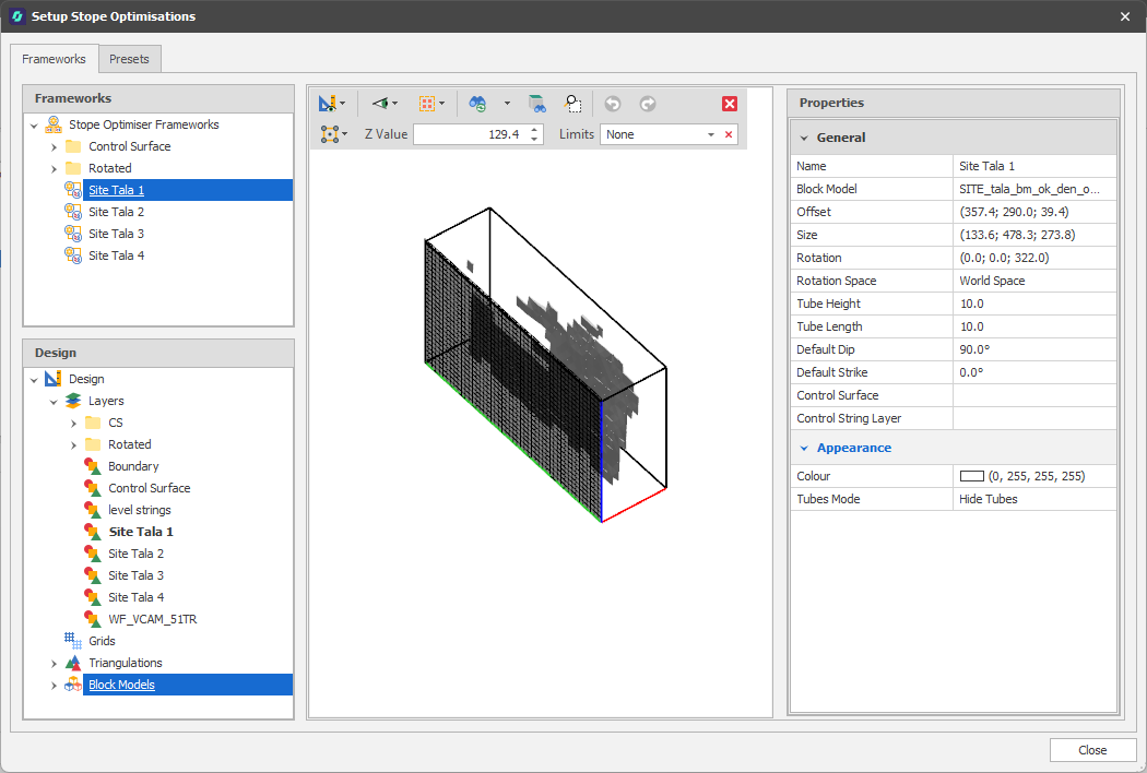
On the Design right-click menu, in the Project Explorer, you can now select Setup | Stope Optimisations to setup the design frameworks and presets for stope optimisation.
When considered in cross-section relative to the direction of stoping, some stoping methods require the stopes to be generated within the constraints of a regular grid pattern or framework. Advance supports this by allowing you to specify the cross-sectional design requirements relative to a two-dimensional grid pattern, along with the position and orientation of that grid relative to the target ore body. It then projects “tubes” from the cells of the grid into the ore body and cuts these tubes into thin slices, for which the economic values are determined.
The quantities and starting locations for the tubes are defined by the framework. The framework may be oriented with respect to the target block model as required to ensure that the stopes are generated in the appropriate direction, which will be orthogonal to the plane of the tubing grid and is referred to as the "strike" of the stopes. (This may be different to the geological strike of the ore body.) The cross-sections of the stopes are predetermined by the spacing and inclination of the lines in the framework.
Using the along-strike design minimum and maximum stope lengths, separation, and near and far dilution lengths specified on the Presets tab, the mathematical programming solver recombines the slices to form stopes that satisfy the specified value or grade requirements optimally.
Setup Stope Optimisations
On the Triangulation tab, in the Add group, select Run Stope Optimiser to run the stope optimisation process against the optimisation frameworks and presets you have setup in the Stope Optimisations Setup window.
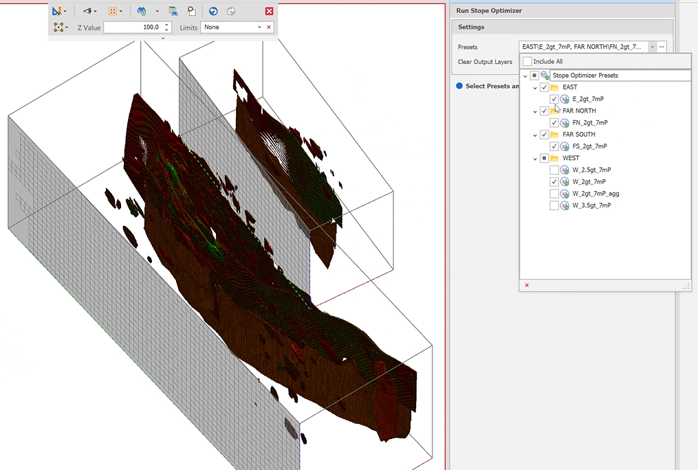
Run Stope Optimiser
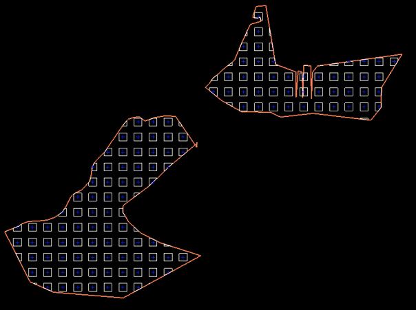
Generate Room & Pillar Shapes
On the Shape tab, in the Add group, a new Generate Room & Pillar Shapes design action can be used to determine where pillars should be located and which areas should remain open as rooms during mining.
A regular pattern which allows for the most cost-effective, productive and safest access to the ore deposits within a target orebody is the end goal.
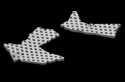
Extrude Shapes to Surface
To facilitate mining at different levels, the generated Room and Pillar shapes can then be extruded to a surface. On the Triangulation tab, in the Add group: Click Extrude Shapes to Surface to take a set of shapes as input and extrude them within a limiting triangulation. (CTRL + L,T)
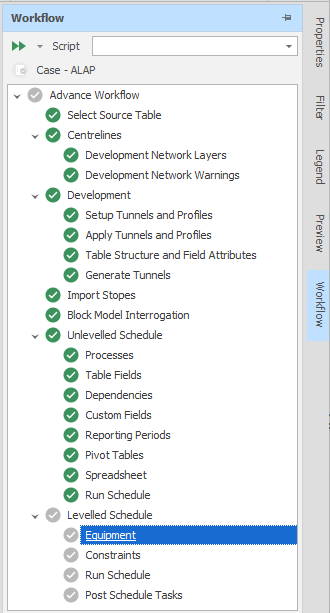
An option to select a scripted workflow has been added to the Workflow dock panel in this release. When there is no script selected, the Advanced Default Workflow (the logical steps that need to be taken to create a schedule) is shown in the Workflow panel.
Each step in the workflow represents an action that needs to be taken in the overall process. Steps may be grouped into folders like a node tree, but only leaf nodes (steps) are executed. Grouping may be useful for conveying the intent of a group of steps.
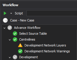
Workflows can be created, modified, and configured using scripts. This means that workflows can be moved between projects by exporting and importing the relevant scripts which create the workflow.
Note that the Scripts panel provides tools that are only applicable to developers, consultants or power users familiar with scripting in C#. For more information. see: Workflow Scripting
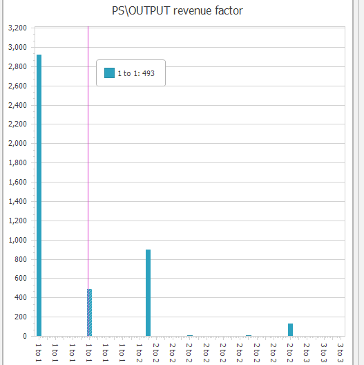
On the Design tab, in the Action group, you can now run a Pseudoflow profit maximisation algorithm using the current scenario/schedule and its dependencies as inputs.
The Pseudoflow algorithm gets the range of solids which when mined produce the maximum value. The Revenue Factor reduces the revenue while keeping the profit the same to “test” how much you have to reduce the revenue before a solid becomes unprofitable. Tasks with a lower revenue factor are “more desirable”.
To check that values have been written to the records in the source table, right-click on the table and select Utilities | Field Statistics:
Animation View Export
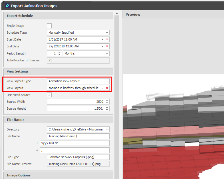
When the Animation Window is open and you select Export | Images from the Import/Export menu on the application window title bar, you can now select a Layout of a specified (Design, Animation View, Engineering Plot, Sectional View) type.
Export Animation Images Preview
When an animation view setting is selected to export will ensure that a consistent image is exported irrespective of the current animation window size.
Alternatively, the user can select the Use Fixed Source check box and specify the size of the image.
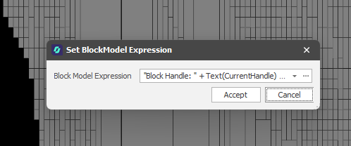
On the Design right-click menu, in the Project Explorer, you can now right-click on a Block Model layer and select options from a Design Tooltip Expression menu to create, edit or clear a tooltip expression for the blocks you have loaded.
In the Set Design Expression dialog, click the drop-down control to create a new expression or edit an existing expression in a Quick Edit window. Alternatively, click the ellipsis to open the Expression Editor in a persistent window:
Engineering Plots
Improvements have been made to the way that Engineering Plot Layouts are configured and visualised.
Keep Plot at Saved Proportions
On the Edit Settings drop-down menu, you can now choose whether to keep the plot layout at its saved proportions or rescale the layout dynamically.
Drafting mode is the default mode (the check box is NOT selected). In this mode, the plot layout is drawn to the current screen size, which can cause offsets if you switch between differently sized screens and resolutions.
Keep Plot At Saved Proportions mode (the check box IS selected) redraws using the saved screen size/span so that text and objects match the original proportions, giving you a reliable preview of how the final exported image will look.
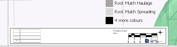
Title Bar/Graphics
You can now load a Title Bar or other graphics into the Animation Layout via a "File" input when you Edit Settings for a selected plot layout. Alternatively, use the "Label Image" input in the Plot Settings dialog to add a Title Bar or Graphic to the overlay. When you click Save As to save a plot layout, any settings you have applied to the overlay (visualisation) are applied to the plot layout.
Create a new layout
You can now select Create New from the Edit Settings drop-down menu to create a new plot layout from scratch. This complements existing Save As functionality which allows you to create a new layout based on an existing one.
In the Animation Window, the same option is available on the Design > Overlay > Engineering Plots right-click menu.
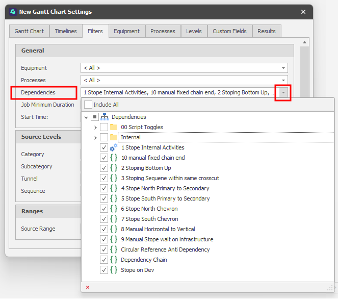
Filter by Dependencies
On the Filters tab of the Gantt Settings window, you can now filter by Dependencies. Use the drop-down to select from Dependencies configured for the current scenario:
Show Dependencies
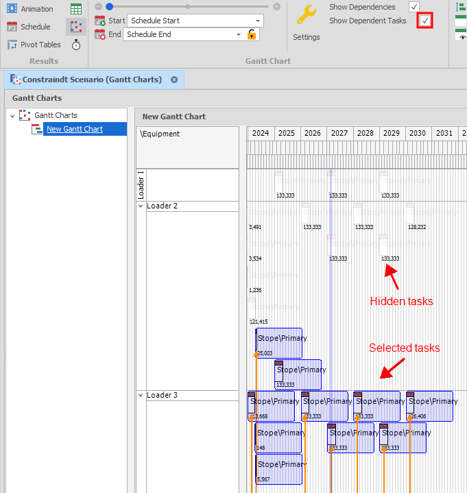
On the Home tab, in the Gantt Chart group, click the Show Dependencies check box to toggle the display of the dependencies you have selected on the Filters tab:
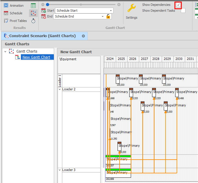
When the Show Dependencies check box is selected, click the Show Dependent Tasks check box to only show selected tasks and their dependent tasks. Tasks that aren't selected will be hidden.
Node Orderings & Groupings
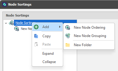
In addition to setting up Node Orderings for a source table, you can now setup Node Groupings via the same Setup | Node Sortings dialog.
Grouping entries comprise of an (Alphanumeric, Numeric, Text) Group Type and a Grouping Expression used to group Table Nodes based on their positions and attributes.
NodeGroupingKey and NodeGroupingKeySafe functions may also be referenced in expressions, for example, when setting the filter condition for a colour set in Source Solids Colours based on node grouping. The function takes a node grouping address and a node from which to retrieve the grouping key.
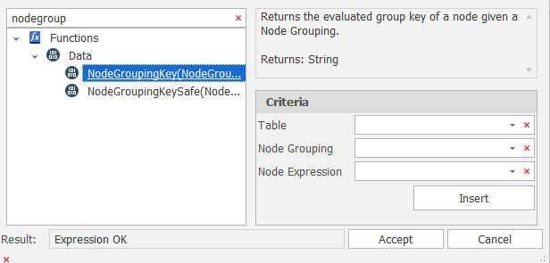
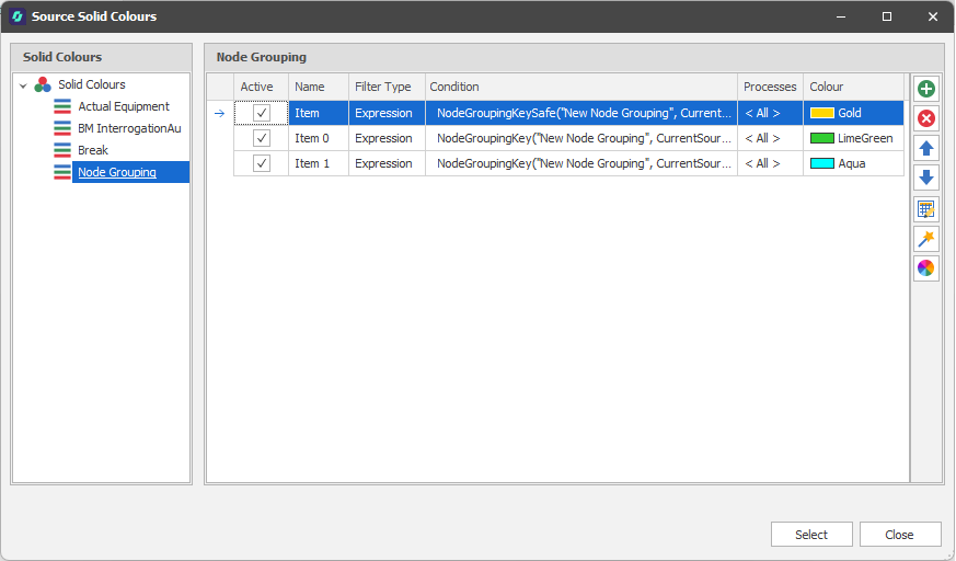
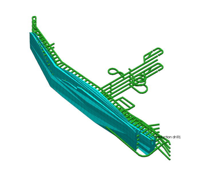
Table Setup & Utilities
You can now right-click on the root node in an open table to access right-click Setup and Utilities menus. You can also access the same options via the ribbon when a table is open
This complements existing Setup and Utilities options available via the Table right-click menu in the Project Explorer.
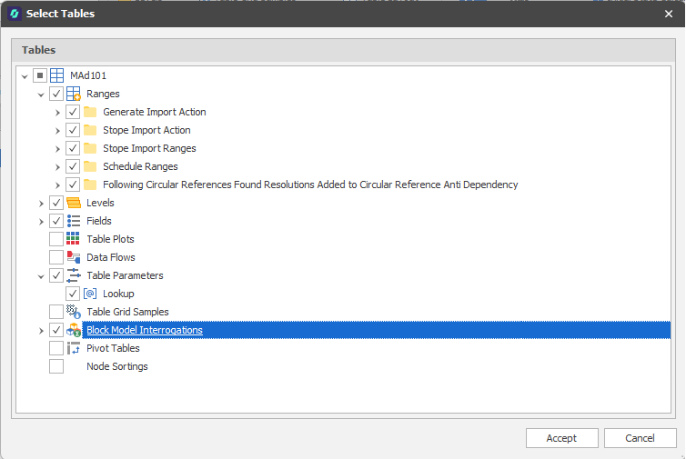
Export Table Structure
When exporting a table structure, you can now export (and re-import) Pivot Tables in XML format.
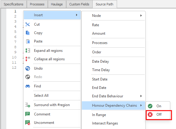
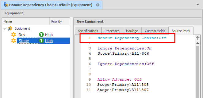
Ignore Dependencies & Honour Dependency Chains
The Source Path syntax has been extended to include an Honour Dependency Chains flag which determines whether predecessor tasks are honoured or not when dependencies are ignored. There are two states:
-
Off - if something is completed with an ignored dependency, subsequent tasks are released.
-
On / Default - if something is completed with an ignored dependency, subsequent tasks are not released until predecessor tasks are completed.
For example, if you have three nodes: Stope\Primary\All\807 → Stope\Primary\All\806→ Stope\Primary\All\805 and you ignore dependencies and complete task 806, the default behaviour will ensure 805 waits on 807 until it is done.
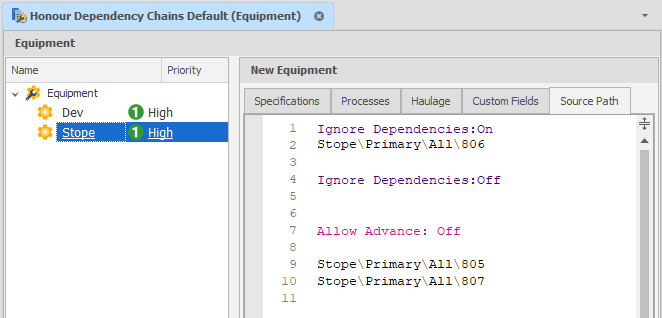
Set Honour Dependency Chains = Off if you want to release all subsequent tasks:
To ensure the default behaviour, explicitly set Honour Dependency Chains = On.
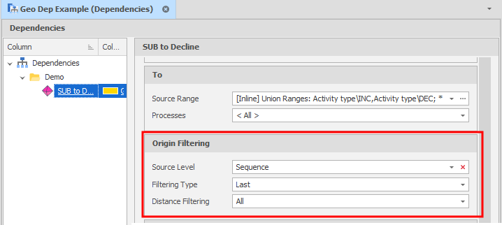
Geometric Dependencies
On the Dependencies tab, in the Add group, when you select Geometric Dependency to use a geometric shape to interactively select dependencies from scheduling solids in the Animation Window, you can now set a filter to limit the search by making the origin of the FROM tasks the first/last node of the specified level.
Post Schedule Tasks
In the Scenario Settings window, on the Post Schedule Tasks tab, a new Export Animation View task can now be added:
Export Animation View 
A view of the animation can now be exported after a schedule run.
The user can specify the file name, image type (PNG, JPEG, BMP), and dimensions.
The user can also specify a view layout and an animation date. If an animation layout or an engineering plot layout that specifies the animation date is specified, this will not be editable.
If a view layout is not specified, the default plan view camera is used.
The exported image can be previewed in the editor:
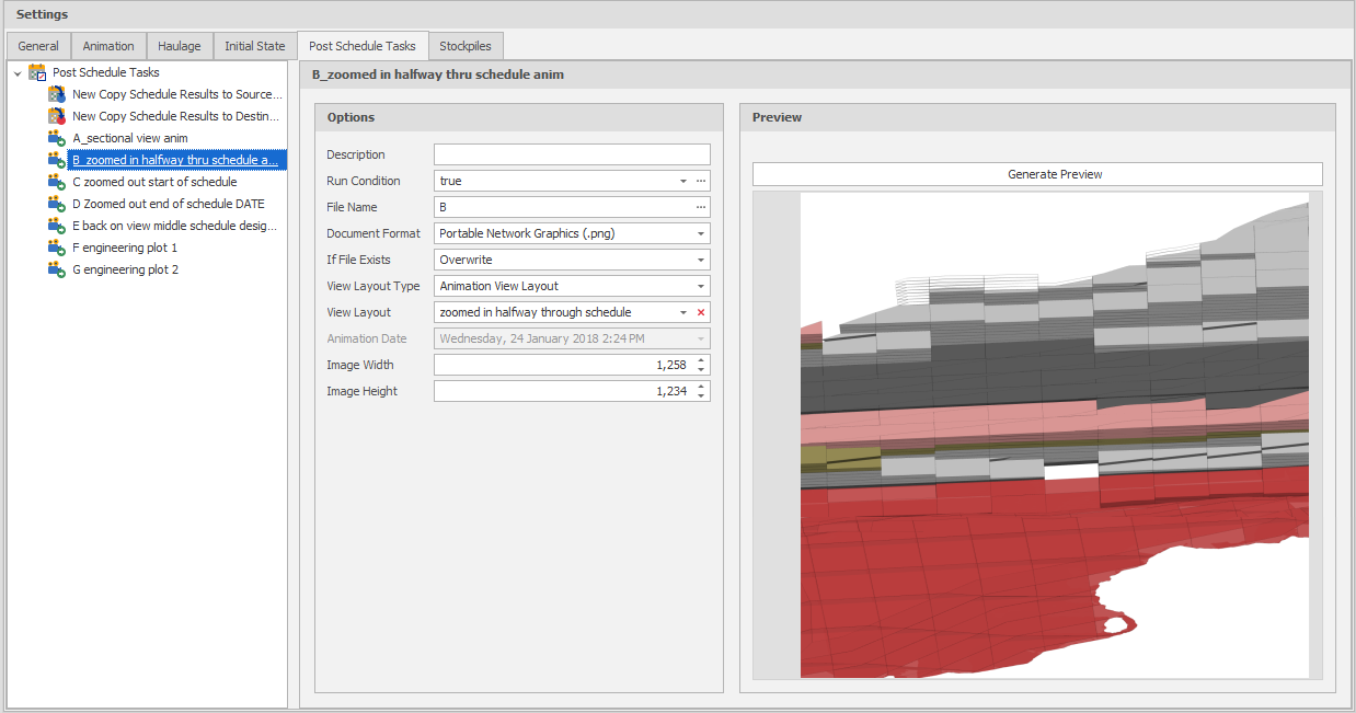
Export Animation Images Preview
Run All
You can now right-click on the Post Schedule Tasks root node (or a folder) and select Run All Post Schedule Tasks to run all active post schedule tasks.
Quality
On the Home tab, in the Setup group, when you select Constraints to apply one or more constraints on the tasks of the schedule, you can now set constraints based on a specified Grade field (or another Quality field) and a time period.
During each time period, a running weight average of the Quality field is calculated at each step (the current velocity). If a given step results in an average value outside of a specified (lower bound - upper bound) range of values, tasks are constrained.
Priority
On the Home tab, in the Setup group:, when you select Constraints to apply one or more constraints on the tasks of the schedule, you can now defines the priority or "level of precedence” that the constraint takes.
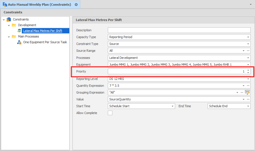
By default all constraints will be adhered to unless the Ignore Constraints flag is set to ON in the Source Path. In addition to setting the Ignore Constraints flag as ON/OFF, the flag may also take a numeric priority value. For example, if Ignore Constraints: 2 is specified in the Source Path, all constraints at that priority or lower will be ignored. For example:
Ignore Constraints:2
will ignore a constraint at priority 2,3,4,5 ...
Ignore Constraints:10
will ignore a constraint at priority 10,11,12, 13 ...
This allows users to specify “safety” constraints (such as not more than 1 equipment per heading, not more than 3 equipment per level), as well as “operational” constraints (such as 100kT per year total, or not more than 10kT on this level in this month) and provides a way of ignoring some or all of the operational constraints, while maintaining all the safety constraints.
Skin Settings
On the General Settings page of the Micromine Advance Settings window, you can now choose between a (Light, Dark) skin and a (Standard, Compact) skin layout. A Light skin and Standard skin layout are the default.
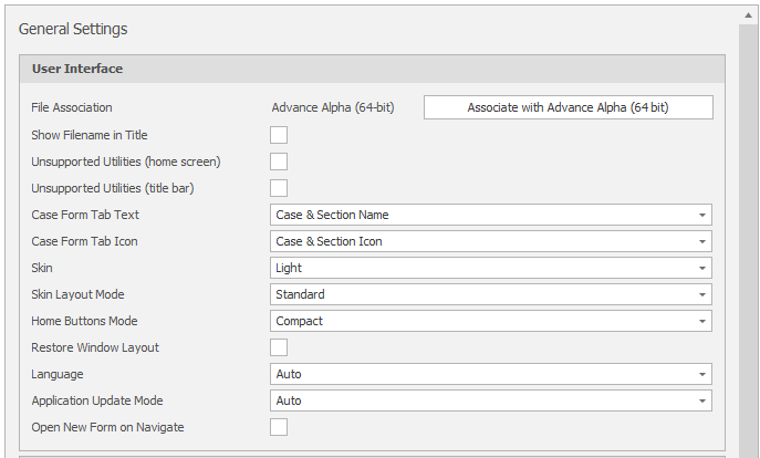
General Settings: User Interface
View Settings
On the View Settings page of the Micromine Advance Settings window, you can now click a Restore Default View Layout button to ensure that all dock panels are restored to their default positions and visibility.
Bulk Editor
Column widths in the Bulk Editor can now be automatically resized to fit the column content and the header text.
This is applied when the ui_bulk_edit_autofit_columns_default user setting is set to True under All Settings .