Animation Layout
When you create an engineering plot layout, it will incorporate the current layout of the Animation View by default. When you Edit Settings, you can review and (if necessary) change the Animation Layout.
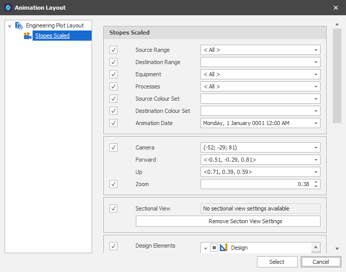
Source/Destination Range
When you filter by Source/Destination Range (on the Home tab, in the Filter group) when the Animation View is open, the Ranges you apply are saved as part of the Animation Layout. You can apply the same or different Ranges to your Plot Layout.
Select the check boxes to filter by Source Range and Destination Range. Accept the defaults or use the drop-down to select a different Source/Destination Range.
Equipment/Processes
When you filter by Equipment/Processes (on the Home tab, in the Filter group) when the Animation View is open, the filters you apply are saved as part of the Animation Layout. You can apply the same or different Equipment and Process filters to your Plot Layout.
Select the check boxes to filter by Equipment and Processes. Accept the defaults or use the drop-downs to apply a different filter.
Source/Destination Colour Sets
When you set Source/Destination Solid Colours on the Animation tab in Scenario Settings (or via the ribbon on the Home tab, in the View group when the Animation View is open, the Source and Destination Colour Set settings you apply in the Animation are saved as part of the Animation Layout.
You can apply the same or different Solid Colour settings to your Plot Layout. Accept the defaults or use the drop-down controls to select Solid Colours for your Source/Destination solids.
Animation Date
When you create a Plot Layout it defaults to the Date on the ribbon (on the Home tab, in the Date group) of the Animation View. Use the drop-down to change the Animation Date.
Camera Settings
The Camera Settings applied in the Animation View are shown here.
Camera
A vector that defines the origin of the viewpoint.
Forward
A unary vector that defines the direction of "forward" in the scene".
Up
A unary vector that defines the direction of "up" in the scene.
Zoom
Use the spin controls to set the zoom factor. The default is 1.0 (full field of view).
Sectional View
Select the check box to include a sectional view (if any, as indicated by the availability of settings):
Remove Sectional View Settings
Click to remove the sectional view from the saved view.
Design Elements
Select the check box to include design elements, for example annotated Shape and Text layers, in the view. You can then select the design layers to include.
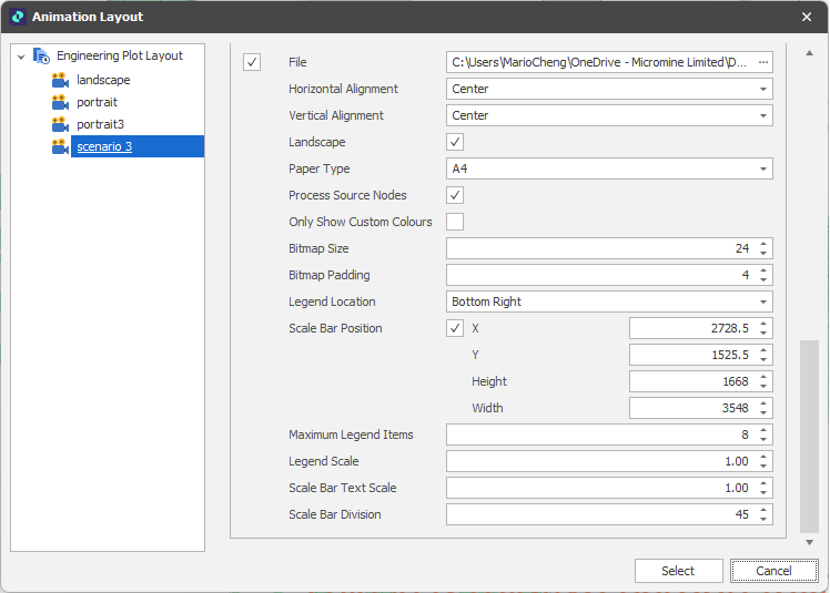
File
Select the File check box to select and load a Title Bar graphic. Deselect the check box to hide the selected graphic
Horizontal/Vertical Alignment
Select a (Near, Centre, Far) alignment option for the Title Bar
Landscape
The default plot paper orientation is Landscape. Deselect the check box if you prefer a Portrait paper orientation instead.
Paper Size
Select a paper/page size. The default is A4. By default, when exporting an engineering plot layout as an image, the image is cropped to the page dimensions.
Process Source Nodes
Select this check box to only show the source nodes that are visible in the animation. All processes are shown in the legend when this check box is not selected.
Only Show Custom Colours
Select this check box to only show the colours applied to animation solids in the legend.
Legend Location
Set the Vertical (Top/Middle/Bottom) and Horizontal (Left, Centre, Right) location of the legend.
Scale Bar Position
You can use the Edit Settings drop-down menu to interactively add a scale bar to the display (when none exists) or reposition an existing scale bar. The same option is available when you right-click in the Animation Window and select Design > Overlay > Engineering Plots.
This populates the scale bar position parameters you see here. Use the check box to toggle the display of the scale bar ON and OFF.
Maximum Legend Items
By default, there are 8 legend bins. Use the spin controls to adjust the number of bins up or down.
Legend Scale
Use the spin controls to increase or decrease the scale of the legend. The default is 1.00.
Scale Bar Text Scale
Use the spin controls to increase or decrease the scale of the text shown along the scale bar. The default is 1.00.
Scale Bar Divisions
Scale bar divisions are calculated automatically based on the scale of the view, however you can use the spin controls to increase or decrease the number of divisions if necessary. The smaller the number, the larger the scale bar and vice versa.
Scale bar divisions are calculated automatically based on the scale of the view, however you can adjust the number of divisions if necessary. The smaller the number, the larger the scale bar and vice versa.
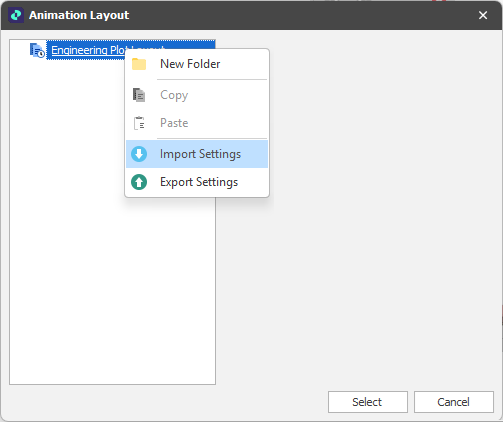
The following options are also available when you right-click on the Engineering Plot Layouts node:
Import Settings
Select Import Settings to import one or more engineering plot layouts that were previously exported in XML file format.
Export Settings
Select Export Settings to export all engineering plot layouts in XML file format.
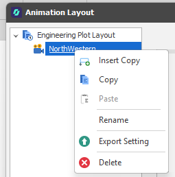
When you right-click on a plot layout, you can also select Export Settings to export the settings of that layout.
Options to Insert Copy, Copy, Rename, Delete and Export are provided which allow you to manage the list of layouts.
Select
Finally, click Select to accept and save any changes.
Cancel
Click Cancel to close the Animation Layout dialog without saving.