Design Network Warnings
When the animation is run, disparities in the order and sequence of mining is an indication that there are broken or erroneous connections in one or more generated networks. Those networks need to be validated to eradicate problems and this can be done at the Design stage, prior to running the animation.
![]()
A full list of Warnings and a summary of how problems can be resolved are listed in the following Table:
You can toggle the display of warnings and apply various settings via the Design | Design Network Warnings | Warnings right-click menu.
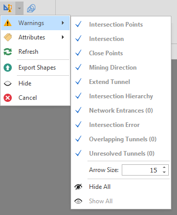
Design Network Warnings Selection
| Warning | Description | Display | |
|---|---|---|---|
| Intersection Points | Points where 2 or more tunnels are intersecting, or where one starts after one ends, they are the start points and/or end points of the connected tunnel centrelines. | Pink dots | |
| Intersection | Where 2 or more tunnels are close enough together to be considered intersecting but there is no intersecting point on the tunnels. | Yellow square with arrow pointing to missing intersection point Y1 next | Default: Add point to this intersection. Alternative: Add point to other segment. |
| Close Points | Where centreline points are too close to each other. | Green square with arrow pointing to extra point point. G2 next | Default: Merge to nearby points. |
| Mining Direction | Shows the tunnel mining direction i.e. how the segments will be linked to each other in sequence. | Blue Arrow | |
| Extend Tunnel | Software automatically creates the intersection links regardless of solid or dashed lines. | Green square | |
| Intersection Hierarchy | Denotes which tunnels are cut from which when removing double counted volumes at intersections. Representative of mining direction. | Purple arrows | |
| Network Entrances | Denotes tunnels with no predecessors, this would indicate tunnels that are immediately available for mining, from surface or from as Builds. | Yellow Arrow | |
| Intersection Error | Two strings are intersecting but there is no intersection point. | ||
| Overlapping Tunnels | Where centreline points are sequenced in a way that segments overlap each other. | Blue square with arrow pointing to overlapping point. | |
| Unresolved Tunnels | A network which creates a loop without a clear starting point. | Highlighted in Red. |
Settings
| Name | Description |
|---|---|
|
Arrow Size |
Use the spin controls to modify the size of the network warning arrows in increments of 0.1. The minimum size is 1 (the default) and the maximum size is 100. When modifying the arrow size value, the size of the arrows in the development network layer will update accordingly. |
|
|
When modifying the arrow size value, the size of the arrows in the network layer will update accordingly. |
|
|
A development_network_warning_arrow_size user setting is available via All Settings. Changing this setting while a network design layer is open will have no immediate effect on the arrows unless a Refresh is clicked. |
|
Refresh |
Refresh the display. |
|
Export Shapes |
Select this option to export shapes to a new layer. A "Network Warnings <n>" named layer is created under Layers in the Design Data pane. |
|
Hide All |
Toggles the display of ALL warnings/errors OFF. |
|
Show All |
Toggles the display of ALL warnings/errors ON. |
Attributes
Some warning/errors may be resolved by assigning the following network attributes:
| Attribute Name | Description |
|---|---|
|
Joiner |
A boolean (true/false) Joiner attribute to be linked to each Centreline Id |
|
Centreline Id |
A unique identifier for each Centreline. |
|
Priority |
The Priority is a numerical method to classify your dependencies by importance. Ranges with Priority 1 will be resolved first, meaning if there are conflicting dependencies between two or more ranges, ranges with lower priority will become circular, rather than randomly resolving the conflict. |