Design Layers
In the Project Explorer, when you right-click on a Table to import solids from design layers, there are two options:
In the Project Explorer, right-click on a Table and select Import | Solids | From Design Layers in this Project.
Select Layers
Select which layers are to be imported (tick/untick the check box alongside the Layers node to quickly select/deselect all layers:
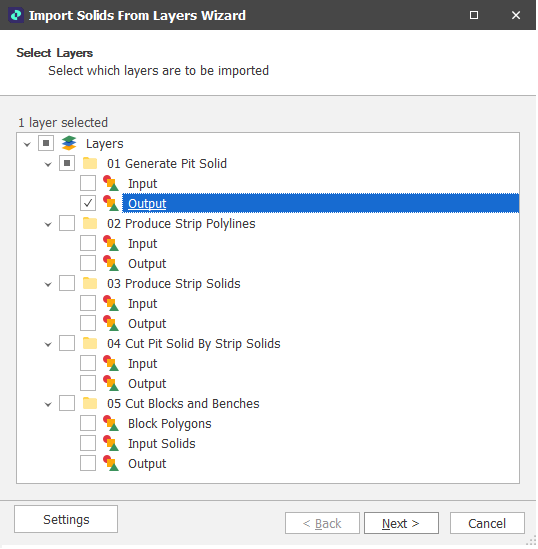
Click Next to continue.
Sample Data
In the Import Wizard, the contents of the file you have selected are shown in the Sample Data pane for review. An option to Bulk Edit the attributes of the file is available.
Note that processing the properties and attributes of a large file may take some time. You will prompted to Continue (or Cancel).
Materials
If you have more than one Material Type, use the Materials pane to use expressions to determine how the solids you are importing will be classified by material. By default, ALL is selected as the material type, meaning you do not want to differentiate by Material Type.
Click the Add icon to enter an appropriate expression that will classify solids by a specified Material attribute.
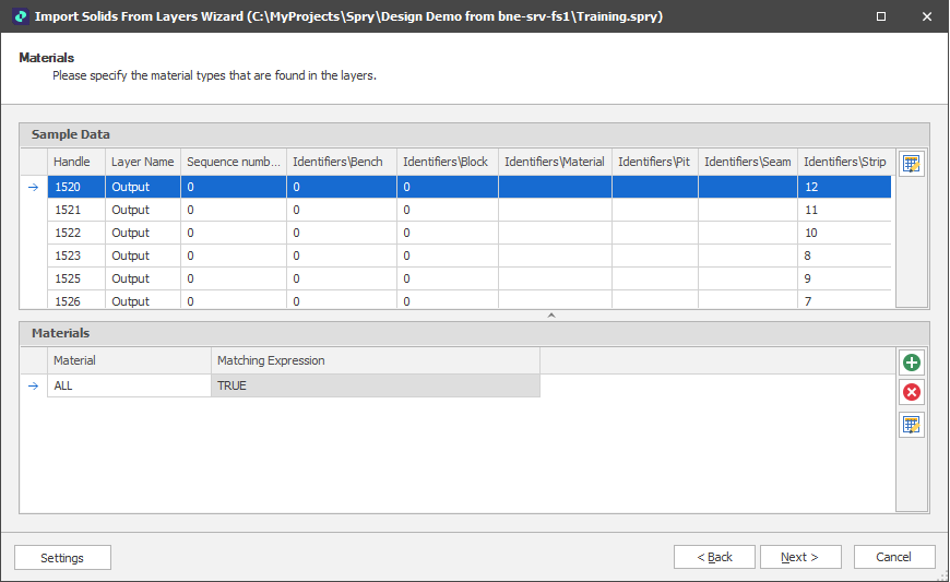
Click Next to continue.
Table Level Expressions
Level
Use the Level Mappings table to map the level structure of the attributes in the imported solids to the levels in the table (i.e. Pit, Stage, Strip, Block, Seam, Bench).
Matching Field/Expression
When you click in a Matching Field/Expression cell, there are two ways in which to match the attributes you want to import to the Levels in the table.
-
Click the drop-down and select the Fields tab to select a field to match to the level:
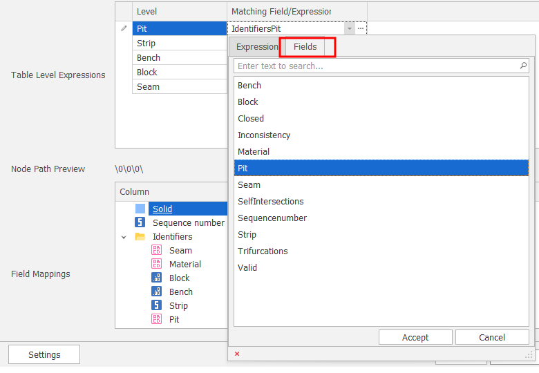
Select a Level field
-
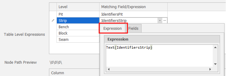
Click the drop-down and select the Expression tab to build a field expression.
For number attributes, replace integers with text, Text(Identifers\Strip), Text(Identifers\Block), etc.
(You can also click the ellipsis button to build a field expression in a separate Expression Editor window.)
Match Level by Expression
![]() Click the Map Levels icon to allow the application to auto map levels to an attribute in the Source file based on Name.
Click the Map Levels icon to allow the application to auto map levels to an attribute in the Source file based on Name.
![]() Click the Bulk Editor icon to make bulk modifications to the Level expressions or fields in the list.
Click the Bulk Editor icon to make bulk modifications to the Level expressions or fields in the list.
Node Path Preview
Based on the mapped levels, a preview of the node path is shown.
Field Mapping
Use the Field Mappings table to map OTHER fields in the data table to the attributes you want to import.
-
Click the drop-down to select a field to match to the import attribute:
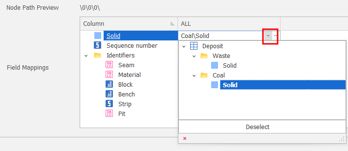
Select a Field
-
Click the ellipsis button to setup fields that can be matched to import attributes.
 Click the Map Attributes icon to allow the application to auto map fields to the attributes in the source file, based on Name.
![]() Click the Bulk Editor icon to make bulk modifications to the attribute mappings.
Click the Bulk Editor icon to make bulk modifications to the attribute mappings.
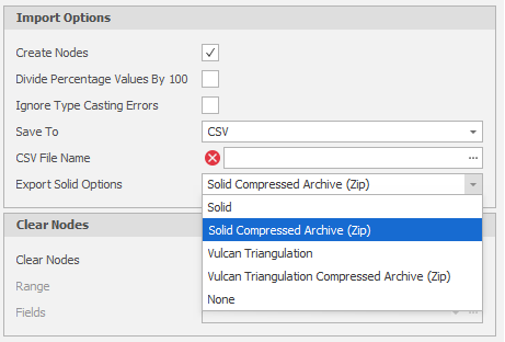
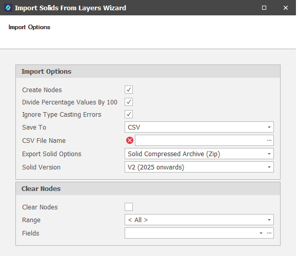
Import Options
The following Import Options are available for selection:
Create Nodes
Select this check box to create nodes as new positions are encountered. Nodes are the progressive positions within a Table Structure, for example, Pit, Stage, Strip, Block, Seam, Bench values:
Alpha/2/3/5/D/100
Divide Percentage Values by 100
The application expects percentages to be in 1 based. If your data stores percentages in 100 based, select this check box to convert them to 1 based. For example, 50% in 100 based is 50, whereas 50% in 1 based is 0.5.
Ignore Type Casting Errors
Select this check box to import data irrespective of mismatches in the data type between imported attributes and layer attributes. Any necessary type conversions will be applied to the imported attributes.
Save To
By default the layer solids you selected will be saved to the target table. You can also select an option to save the solids to a specified CSV file instead.
Export Solid Options
If you choose to save the imported triangulations to a CSV file, the option to export the generated solids alongside the CSV file is also provided. Choose an export format in which to save the solids (or select None).
Clear Nodes
Each Node within a Picked Range is an inclusive type filter, meaning the Nodes you clear are excluded from the Picked Range you selected as the Import Range. Select the Range and the Fields within which you want to clear nodes.
Click Next to proceed with the import. The Import process will will create whatever positions are needed.
Tip: When you are importing data into a table and the Position required does not exist, the application (if you select the option to do so) will append the Position to the end of the list regardless of "logical" ordering. If the application is creating Positions for you, you should ensure that you re-order once completed.
For more information, see Levels
Settings
Select Settings | Export to export mappings and other settings to an XML file. This file can subsequently be used to import the same data into other projects/models.
Restart
Click Restart (at the lower left of the Wizard window) to proceed with another import and return to the Import Options page. From there you can adjust your import settings and re-import if needed.
In the Project Explorer, right-click on a Table and select Import | Solids | From External Project.
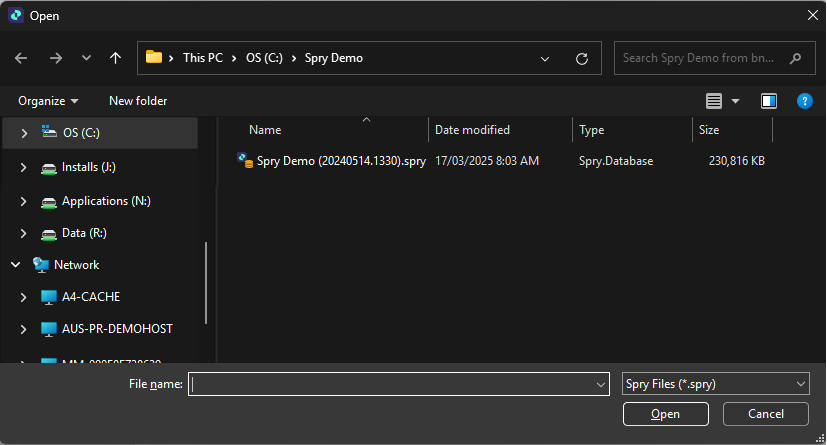
Select Project
You will be prompted to select the project to import layers from:
Select Layers
Select which layers are to be imported (tick/untick the check box alongside the Layers node to quickly select/deselect all layers:
Click Next to continue.
Sample Data
In the Import Wizard, the contents of the file you have selected are shown in the Sample Data pane for review. An option to Bulk Edit the attributes of the file is available.
Note that processing the properties and attributes of a large file may take some time. You will prompted to Continue (or Cancel).
Materials
If you have more than one Material Type, use the Materials pane to use expressions to determine how the solids you are importing will be classified by material. By default, ALL is selected as the material type, meaning you do not want to differentiate by Material Type.
Click the Add icon to enter an appropriate expression that will classify solids by a specified Material attribute.
Click Next to continue.
Table Level Expressions
Level
Use the Level Mappings table to map the level structure of the attributes in the imported solids to the levels in the table (i.e. Pit, Stage, Strip, Block, Seam, Bench).
Matching Field/Expression
When you click in a Matching Field/Expression cell, there are two ways in which to match the attributes you want to import to the Levels in the table.
-
Click the drop-down and select the Fields tab to select a field to match to the level:
Select a Level field
-
Click the drop-down and select the Expression tab to build a field expression.
For number attributes, replace integers with text, Text(Identifers\Strip), Text(Identifers\Block), etc.
(You can also click the ellipsis button to build a field expression in a separate Expression Editor window.)
Match Level by Expression
![]() Click the Map Levels icon to allow the application to auto map levels to an attribute in the Source file based on Name.
Click the Map Levels icon to allow the application to auto map levels to an attribute in the Source file based on Name.
![]() Click the Bulk Editor icon to make bulk modifications to the Level expressions or fields in the list.
Click the Bulk Editor icon to make bulk modifications to the Level expressions or fields in the list.
Node Path Preview
Based on the mapped levels, a preview of the node path is shown.
Field Mapping
Use the Field Mappings table to map OTHER fields in the data table to the attributes you want to import.
-
Click the drop-down to select a field to match to the import attribute:
Select a Field
-
Click the ellipsis button to setup fields that can be matched to import attributes.
Click the Map Attributes icon to allow the application to auto map fields to the attributes in the source file, based on Name.
![]() Click the Bulk Editor icon to make bulk modifications to the attribute mappings.
Click the Bulk Editor icon to make bulk modifications to the attribute mappings.
Import Options
The following Import Options are available for selection:
Create Nodes
Select this check box to create nodes as new positions are encountered. Nodes are the progressive positions within a Table Structure, for example, Pit, Stage, Strip, Block, Seam, Bench values:
Alpha/2/3/5/D/100
Divide Percentage Values by 100
The application expects percentages to be in 1 based. If your data stores percentages in 100 based, select this check box to convert them to 1 based. For example, 50% in 100 based is 50, whereas 50% in 1 based is 0.5.
Ignore Type Casting Errors
Select this check box to import data irrespective of mismatches in the data type between imported attributes and layer attributes. Any necessary type conversions will be applied to the imported attributes.
Save To
By default the layer solids you selected will be saved to the target table. You can also select an option to save the solids to a specified CSV file instead.
Export Solid Options
If you choose to save the imported triangulations to a CSV file, the option to export the generated solids alongside the CSV file is also provided. Choose an export format in which to save the solids (or select None).
Clear Nodes
Each Node within a Picked Range is an inclusive type filter, meaning the Nodes you clear are excluded from the Picked Range you selected as the Import Range. Select the Range and the Fields within which you want to clear nodes.
Click Next to proceed with the import. The Import process will will create whatever positions are needed.
Tip: When you are importing data into a table and the Position required does not exist, the application (if you select the option to do so) will append the Position to the end of the list regardless of "logical" ordering. If the application is creating Positions for you, you should ensure that you re-order once completed.
For more information, see Levels
Settings
Select Settings | Export to export mappings and other settings to an XML file. This file can subsequently be used to import the same data into other projects/models.
Restart
Click Restart (at the lower left of the Wizard window) to proceed with another import and return to the Import Options page. From there you can adjust your import settings and re-import if needed.
In the Design Data pane, when you right-click on the Layers node, you can select an option to import layers from an external project:
To import layers in an external project and display them as design layers in the current project:
-
In the Design Data pane, right-click on the Layers node or the name of a folder and select Import | Layers from External Project.
-
In the File Explorer, you will be prompted to select the project to import layers from.
-
In the Import Solids from Layers wizard, select the layers to import and then click Next.
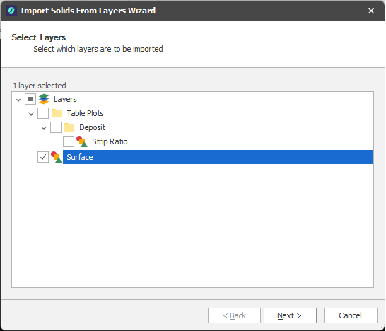
-
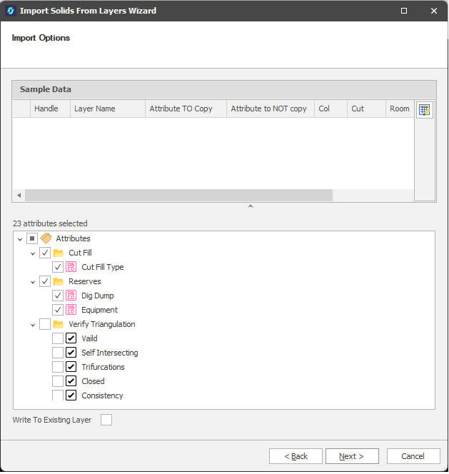
Select the Attributes you want to import.
Note: For third-party file imports, the contents of the file you have selected for import are shown in the Sample Data pane for review. This may not be applicable when importing Micromine Spry layers.
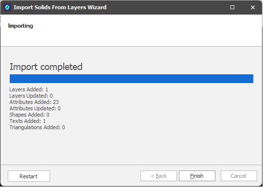
A completion message is displayed once the import has finished.
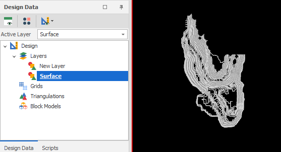
-
Display the imported layers and verify that the attributes you selected have been imported:
Restart
Click Restart (at the lower left of the Wizard window) to proceed with another import and return to the Import Options page. From there you can adjust your import settings and re-import if needed.