Data Flows
![]()
The Data Flow Window has four main areas:
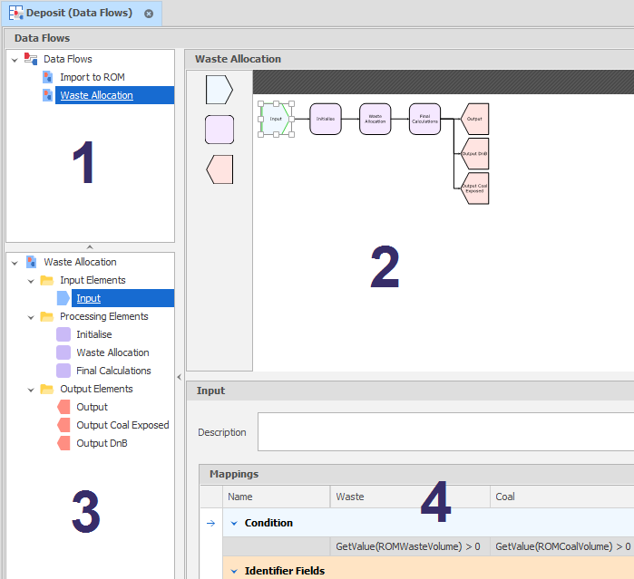
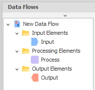
1. The data flows you have created for a table are listed top left.
The Data Flows pane contains a list of the data flows you can run on the underlying data table. The order of the data flows in the list is only important if you select Run All to run all data flows.
![]()
You can click and drag a data flow with the mouse to change its order.
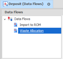
To create a data flow, right-click on the Data Flows node and select New Data Flow.
You can also right-click on a data flow to change its Graph (Settings). The same option is available on the Home tab, in the Graph group, when a data flow is selected.
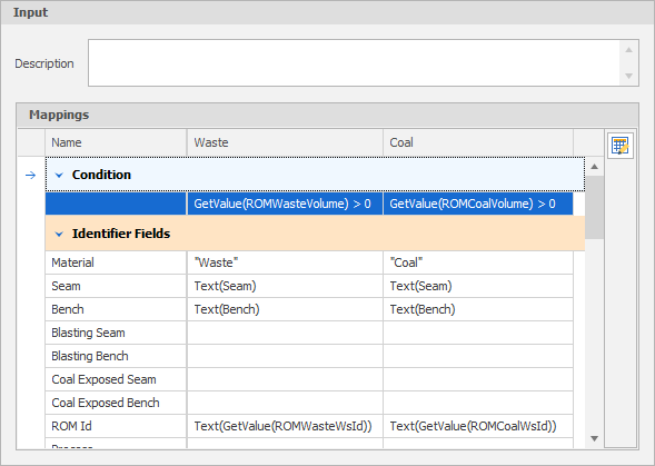
2. Each data flow is defined by adding "elements" to a diagram.
If you've ever created a flowchart, you'll already have noticed that a data flow diagram is similar. Typically, a data flow will have (at a minimum) one Input element, one Processing element and one Output element.


Elements are added to the diagram by dragging them onto the diagram from an Element Selection panel to the left of the diagram.
To link from the right-hand side of one element to the left-hand side of the next element, select the Connector tool on the Home ribbon, in the Diagram group, to snap to the mid-point on the right-hand side of one element and then click and drag the mouse to snap to the mid-point on the left-hand side of the next element.
![]()
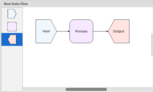
The window is resizable. Horizontal and vertical scroll bars can also be used to navigate the display. You can also use the mouse wheel or the options on the Home tab, in the Zoom group, to resize the diagram and its elements.
3. Elements added to the diagram are also listed in an Elements pane.
Default folders for each type of element are initially empty.
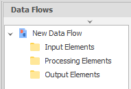
Elements added to the diagram (in Step 2) are listed under their respective folders. You can right-click on an element and select Rename to change the default name.
4. When an element is selected, the properties of the element are shown below the diagram.
5. A Preview pane to the right of the diagram is also opened.
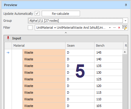
The information displayed in the Preview pane will depend on the type of element:
| Input | The input source data that has been retrieved from the underlying data table based on the Materials and Fields selected. See: Input Elements |
| Processing | The "Before and After" of the processing of the input source data. See: Processing Elements |
| Output | The unit results generated as a result of processing. See: Output Elements |
Warnings or Errors are displayed if a step has been missed during the setup of that element, for example, when the grouping expression of an Input element has been missed or a connector is missing.
Tip: A quicker way to setup a data flow is to right-click on an existing data flow and select Insert Copy. You can then modify and add to the elements that already exist in the copied data flow.
To see how a data flow is used with table parameters, see: Example