Generate Multiple Fans
![]()
Until you enter Edit Ring mode and select a ring, drillholes will not be displayed unless the option to Display hole numbers is selected on the Drillhole Labels tab of the Ring Design form.
To create multiple pivot fans:
-
In Vizex, open a Ring Design layer and select the ring you want to edit.
-
On the Mining | Ring Design tab, in the Drillhole group, select Generate Fan | Generate Multiple Fans to enter Edit Ring mode.

The orientation of the display will change so that it is orthogonal to the selected ring plane. If holes already exist on the current ring, they will be displayed.
The application will then display instructions within the status bar.
-
To add a fan, begin by selecting the position of the drill rig.
-
Once the rig is positioned, select the position for the boom of the rig. Define the range for the first fan. The CTRL key can be used in combination with the arrow keys to modify the increment: CTRL will move by increment / multiplier.
-
Define the start/end range for the first fan. You can press the Esc key to cancel the process and start again. Upon completing this step, you can complete the steps required to define the first fan.
-
Select the position of the drill rig for the next fan. Note that you can hold the X or Y keys to lock the movement of the rig to the X or Y axis in the viewing plane. For example, this will allow you to ensure the pivots points of different fans are aligned.
-
Once the rig is positioned for the second fan you can define the start/end range for the fan. Upon completing this step, you can right-click to complete the interactive process. Doing so will open the Generate Fan dialog.
You can continue defining additional fans by repeating steps 3-7 again.
Note:
-
The application prevents intersections between the edges of arcs so that the arcs cannot overlap in any way.
-
It is important to note that the application implicitly treats ALL fan arcs as if they were defined in the same direction. The direction will be based on the direction of the first arc.
The reason for this is that the last hole of Fan 1, for example, will not be able to be positioned with the first hole of Fan 2 if Fan 2 was created in the opposite direction.
-
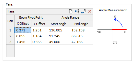
The grid within the Fans group box of the Generate Fans dialog can be used to adjust the boom pivot point offset or angle range of any fan.
-
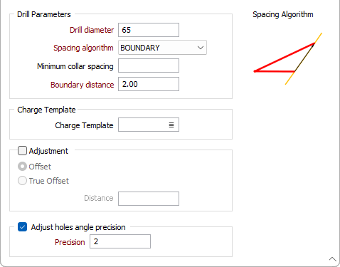
Enter the drill diameter, the toe spacing, and the spacing algorithm to be applied when generating the fans. The drill diameter is expressed in millimetres. The toe spacing is expressed in metres. See: Hole spacing algorithms
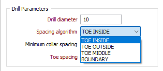
When non-parallel holes are generated, you can specify a minimum collar spacing which is the minimum distance between the holes along the DRIVE boundary. If the calculated distance is less than the minimum collar spacing, the minimum is applied instead.
-
You can use the Preview button to preview the changes and inspect the result before adding the holes
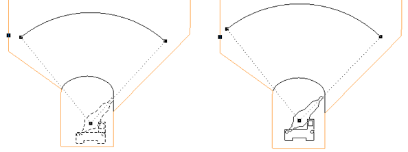
Drill Rig Shape and Positioning
When you have setup a Drill Rig Restriction in the Ring Design Options form:
An outline of the rig shape is drawn around the cursor when new holes are designed. The rig outline is a solid line when the rig lies inside the drive (and is, therefore, in a valid position). If any part of the rig shape falls outside of the drive, a dashed line is shown.
You can use the keyboard to move or nudge the boom (the rotatable part of the rig) when designing new holes in Ring Design.
In Vizex, you can use the keyboard arrow keys to nudge selected strings or points in the plane of the screen, by a specified increment, or by a specified increment and multiplier.
The Up and Down arrows move the selected strings or points in a positive and negative Y direction. The Right and Left arrows move the selected strings or points in a positive and negative X direction.
The CTRL key can be used in combination with the arrow keys to modify the increment:
- CTRL will move by increment / multiplier.
Nudge increment and multiplier values are defined as String Editing Options (Tools | Options | Vizex | String Editing). The nudge increment defaults to 1.0. The nudge increment multiplier defaults to 10.
For example, if the nudge increment is set to 1, and the nudge increment multiplier is set to 10, the arrow keys will move the rotatable part of the rig by 1, while CTRL + arrow keys will move it by 0.1.
The rig shape can also be rotated using the arrow keys:
- SHIFT + LEFT/RIGHT ARROW keys will rotate by 5 degrees.
- SHIFT + UP/DOWN ARROW keys will straighten the rig (point the rig up/down).
- SHIFT + CTRL + LEFT/RIGHT ARROW keys will rotate by 1 degree.
Once a valid rig position is selected and the mouse button is pressed, the rig shape will be anchored at that position. As the mouse is moved around, the boom of the rig shape rotates about the boom pivot point, again changing how the lines of the rig shape are drawn.
When the pivot point and the hole angles are edited, some basic checks are made against the rig shape to ensure that the rig position/boom rotation is valid.
For fans, the boom of the rig shape continues to rotate around the boom pivot point, again being drawn as a solid line when the end hole direction is valid for the rig shape.
If you release the mouse button in an invalid rig position/boom rotation based on the hole direction, the tool will do nothing and you must select a valid direction and press the mouse button.