Generate Parallel Fan
Until you enter Edit Ring mode and select a ring, drillholes will not be displayed unless the option to Display hole numbers is selected on the Drillhole Labels tab of the Ring Design form.
To create parallel holes:
- On the Mining | Ring Design tab, in the Edit group, click Edit Ring to enter Edit Ring mode. If no ring is selected, the Selection Assistant will prompt you to select the ring you want to edit.
![]()
-
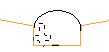
The orientation of the display will change so that it is orthogonal to the selected ring plane. If holes already exist on the current ring, they will be displayed. On the Mining | Ring Design tab, in the Drillhole group, click Generate Parallel Fan:
![]()
-
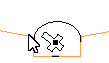
Digitise an initial pivot point. If you have setup a drill rig restriction, the pivot point will be an offset of the Boom Pivot Point, and must be located within the drive boundary. For parallel holes, the pivot point is offset for each hole situated in parallel, at a specified hole angle.
-
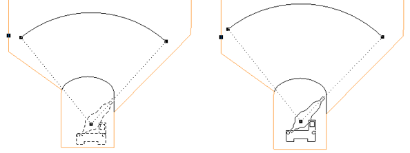
Once an initial pivot point has been digitised, move and then drag the mouse to define the rectangular area the holes will cover.
- CTRL will move by increment / multiplier.
- SHIFT + LEFT/RIGHT ARROW keys will rotate by 5 degrees.
- SHIFT + UP/DOWN ARROW keys will straighten the rig (point the rig up/down).
- SHIFT + CTRL + LEFT/RIGHT ARROW keys will rotate by 1 degree.
When you have setup a Drill Rig Restriction in the Ring Design Options form:
An outline of the rig shape is drawn around the cursor when new holes are designed. The rig outline is a solid line when the rig lies inside the drive (and is, therefore, in a valid position). If any part of the rig shape falls outside of the drive, a dashed line is shown.
You can use the keyboard to move or nudge the boom (the rotatable part of the rig) when designing new holes in Ring Design.
In Vizex, you can use the keyboard arrow keys to nudge selected strings or points in the plane of the screen, by a specified increment, or by a specified increment and multiplier.
The Up and Down arrows move the selected strings or points in a positive and negative Y direction. The Right and Left arrows move the selected strings or points in a positive and negative X direction.
The CTRL key can be used in combination with the arrow keys to modify the increment:
Nudge increment and multiplier values are defined as String Editing Options (Tools | Options | Vizex | String Editing). The nudge increment defaults to 1.0. The nudge increment multiplier defaults to 10.
For example, if the nudge increment is set to 1, and the nudge increment multiplier is set to 10, the arrow keys will move the rotatable part of the rig by 1, while CTRL + arrow keys will move it by 0.1.
The rig shape can also be rotated using the arrow keys:
Once a valid rig position is selected and the mouse button is pressed, the rig shape will be anchored at that position. As the mouse is moved around, the boom of the rig shape rotates about the boom pivot point, again changing how the lines of the rig shape are drawn.
When the pivot point and the hole angles are edited, some basic checks are made against the rig shape to ensure that the rig position/boom rotation is valid.
For fans, the boom of the rig shape continues to rotate around the boom pivot point, again being drawn as a solid line when the end hole direction is valid for the rig shape.
If you release the mouse button in an invalid rig position/boom rotation based on the hole direction, the tool will do nothing and you must select a valid direction and press the mouse button.
As you generate parallel holes you can also snap to an existing pivot point or hole. See: Snapping
-
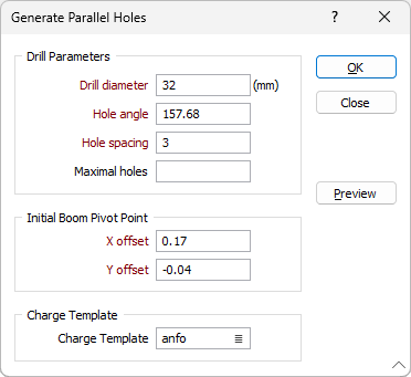
When you release the mouse button, the Generate Parallel Holes dialog is displayed:
-
Enter the drill diameter, hole angle, and the hole spacing to be applied when generating parallel holes. The drill diameter is expressed in millimetres. The hole spacing is expressed in metres.
Given the hole spacing, optionally specify the maximum number of holes which should be added to the region in the Maximal holesfield.
- If necessary, adjust the position of the Initial Boom Pivot Point by setting the X Offset and Y Offset values. The displayed coordinates represent an offset from the drive string. The pivot point is measured from the intersection point of the drive string and the ring plane (the drive "centre line").
If the pivot point is repositioned outside the drive, an error message will be displayed and you will be prompted to re-enter the pivot point offset coordinates.
The position of subsequent pivot points are automatically calculated based upon the hole spacing and the rectangle you have defined in the graphic display.
-
Select the Charge Template of the explosives to be used for charging. Charge details can be included in a ring design report or plot.
-
Click the Preview button to see a preview of the holes that will be generated.
-
Finally, click the OK button to generate parallel holes.
You are not restricted to creating one set of parallel holes. You can generate parallel holes as many times as you like, and, where appropriate, combine them with fanned holes. To ease the process, you can snap to an existing pivot point or hole. See: Snapping
While you can use the mouse to move and rotate holes in the display, it is preferable to adjust the position and the angle of selected holes in the Properties window.
If you need to modify the position and angle of multiple holes, you can use the Adjust Multiple Drillholes tool on the Mining | Ring Design tab, in the Drillhole group. Depending on the changes you want to make, it may be easier to delete those holes and recreate them using the Generate tools in the same group.