Edit Drillholes
![]()
To modify the position of multiple drillholes and/or pivot points whilst maintaining the toe boundary distance, use the Edit Multiple Drillholes or the Edit Fan tool.
Until you enter Edit Ring mode and select a ring, the holes will not be displayed unless the "Always display drillholes" option is selected on the Drillhole Labels page of the Ring Design Options form.
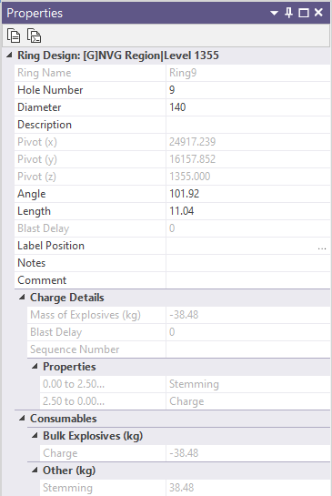
When you click on a hole to select it, its properties are displayed in an editable panel which shows the drill diameter, pivot point coordinates, hole angle, hole length, charging and blast delay information.
|
|
Note that while you can edit the length, angle, and diameter of a hole, you cannot move or rotate a hole interactively until you click Edit Drillholes or Edit Multiple Drillholes on the Mining | Ring Design tab, in the Drillhole group. This is a safeguard which makes it less likely that a hole will be accidentally moved. |
| Rotate | When you click and drag the toe of a hole with the mouse, you can effectively change the angle of the hole by rotating it left or right. The pivot point will remain fixed. (While you can also change the angle by clicking and dragging the hole collar, this is not normal practice). |
| Move | When you click and drag any other part of a hole with the mouse, you can move it to a new location. The length of the hole is adjusted so that it automatically snaps to the ring boundary and the position of the pivot point is automatically adjusted. |
Any changes made in the display will be reflected in the Properties window.
In general, using the Properties window to adjust the position and angle of individual holes is preferred. If you need to make a large number of modifications it is easier to use the Edit Multiple Drillholes tool. Alternatively, delete holes and reuse the Generate Parallel Fan and Generate Angled Fan functions.
Rig Preview
When the selected drillhole is modified, the shape of the rig will appear within the drive profile. This provides a visual cue of the location of the rig.
Note that any new pivot point (resulting from edits via the collar or other parts of the hole) will be restricted to horizontal offsets of the original pivot point.
Delete holes
On the Mining | Ring Design tab, in the Drillhole group, a Delete Drillholes tool can be used to delete holes by selecting one or more (drive and/or ring) objects which contain the holes you want to delete. You can use this tool without necessarily entering Edit Ring mode.
![]()
When the display is in Edit Ring mode, holes can be selected and deleted in a number of ways:
-
To delete a single hole, click on it to select it, then click the Delete button.
-
To delete multiple holes use the CTRL key with the mouse to select the holes you want to delete. Alternatively, drag the mouse to define a rectangle that encloses the holes you want to delete. Click the Delete button.
-
To delete holes in increasing hole order (based on the current clockwise or anti-clockwise numbering direction):
-
Click on the hole you want to delete FROM.
-
Hold down the CTRL key and click on the hole you want to delete TO.
All holes that fall between the delete FROM and TO holes, including the FROM and TO holes, will be deleted when you click the Delete button.
Undo
You will not be prompted to confirm your deletions. If objects are deleted inadvertently, use the Edit | Undo (CTRL Z) option to recover.
Undo can be used to undo any editing operations, not just deletions.
Save your changes
You must explicitly save any changes you make to the objects in the Ring Design layer. This applies to editing rings, holes, and ring boundaries. If you do not save your changes, you will be prompted to do so when you either close the display layer, exit Vizex, or exit the application.