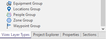
Equipment Group
Double click on Equipment Group in the Vizex Layer Types panel to view Equipment Group properties.
The Properties dialog has four tabs:
- Equipment. This tab defines the general display of equipment units.
- Trail. Equipment unit movements between locations over time are displayed as a trail.
- Z Values. Define how the equipment symbol is spatially positioned relative to the RL or Z coordinates of the associated topographic or pit surface wireframe.
- Radius. Define the radius of influence of the equipment unit during the hauling cycle—loading, queuing and hauling.
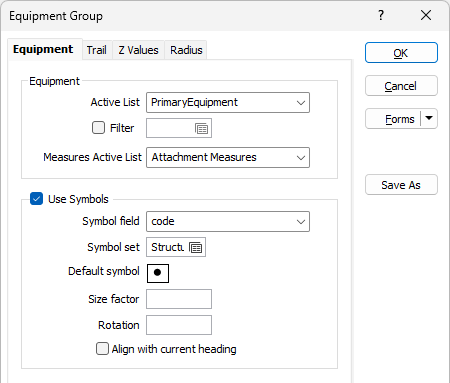
Equipment
Active List
The equipment active list options available to you are configured by an administrator using the Reference Edit service.
Filter
Select the check box and double-click in the Filter input box if you want to define a filter. For example, you want to restrict the display of equipment to haul trucks operating underground.
Measures Active List
Select the Measures active list whjich applies to the Equipment Group.
Symbols
Select the Use Symbols check box to enable symbols to be displayed.
Symbol field
Enter the name of the field (in the file) containing the data that will control which symbol is displayed. The symbol set, that is associated with this field, maps symbols to text strings or numeric ranges. For each record in the file, the symbol is determined by the value in this field.
Symbol set
Double click (F3) to select the set that will be used to control the symbol that will be displayed. The symbol set maps symbols to text strings or numeric ranges. This determines a symbol for each value in the chosen (mapped) field. Right click (F4) to create or edit a symbol set.
Default symbol
Double-click the Symbol icon to choose a symbol. You can source symbols from any TrueType or OpenType font.
Size factor
Enter the factor that will be used to control the size of the displayed symbol. The default is 1.0.
Rotation
Enter the rotation angle values (0-360°) for the displayed symbols. A value of 0 will display the symbol in its natural orientation. A value of 90 will display the symbol rotated 90° in the clockwise direction.
Align with current heading
Select this option to align the displayed symbols with the heading or direction of the units.
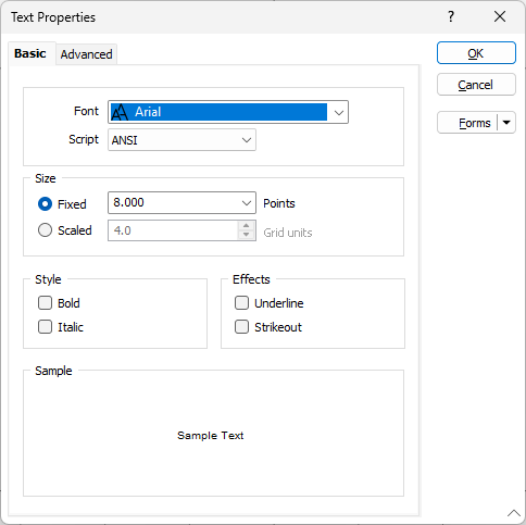
Text
Display field and Text properties
Specify the name of a Display field containing point annotation values. Typically, this will be the Description defined for each unit in Reference Edit.
If you do not select a filed from the Display field drop down, only the chosen symbol will be displayed.
Double click the Text Properties preview to select a font to be used to display the text annotation.
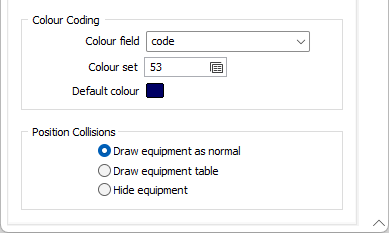
Colour Coding
Colour field
Enter the name of the field that contains values which will control the display colour. For example this could be a field with a status for the unit.
The colour set associated with this field maps colours to text strings or numeric ranges. For each record in the file, the display colour is determined by the value in this field.
Colour set
Double click (F3) to select the set that will be used to control the collar display colour. The colour set maps colours to text strings or numeric ranges. This determines the colour for each value in the colour field. Right click (F4) to create or edit a colour set.
Default colour
Double click (F3) to select the colour to be used when a colour set is not defined, or when the value in the colour field is not mapped in the colour set.
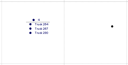
Position Collisions
Select the required display for position collisions; for instances where multiple units are recorded at the same coordinates (waypoint).
-
Draw equipment as normal - Will not take into account the overlapping of position. Equipment will be displayed as normal.
-
Draw equipment table - Will display labels as a table if multiple equipment have the same coordinates, and display the default symbol instead of the Equipment icon, so there is no overlap of display.
-
Hide equipment - Overlapping objects will be hidden. If equipment is double clicked in the Vizex layer tree, the selection will be displayed in Vizex and the camera will pan to place it on screen if the position is out of view. If the equipment is deselected, it will be hidden once again.