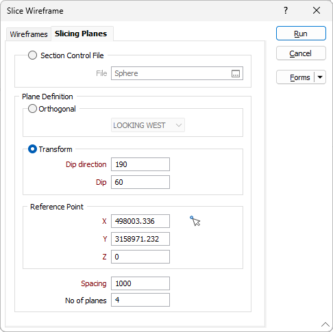
Slicing Planes
Use the Slicing Planes tab of the Slice Wireframe form to specify how the cutting plane is defined. There are three options:
Section Control File
Select the Section Control File option to slice the wireframe using the sections defined in a section control file. Click the ellipsis button (or double-click) to navigate to the location of the File that contains the sections you will use to slice the wireframe.
Plane Definition
Select an Orthogonal or Transform plane definition.
Orthogonal
Select the Orthogonal option to slice the wireframe using an Orthogonal (LOOKING WEST, LOOKING NORTH, PLAN) projection plane.
Transform
Select the Transform option to slice the wireframe using a transform projection plane.
Enter the Dip direction and Dip values that will be used to calculate the transformation. The Dip value entered must be a positive number.
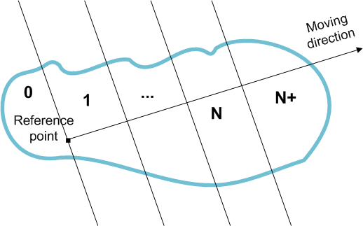
Reference Point
For the Orthogonal or transform plane you have defined, define a reference point which will be used as the origin of the plane from which the levels will be created.
Where available, you can use the Pick Point in Vizex button to select the point coordinates.
Spacing
Enter a spacing which will determine the thickness of each slice.
No. of planes
Optionally specify the number of planes required. If no number is specified, the function will slice from the specified reference point, slicing in the specified direction, until the end of the wireframe is reached.
To generate slice strings, select Wireframe | Generate Strings | Planar Intersection Strings.
Run
When you have specified the inputs and outputs to the process and defined the cutting planes, click Run to begin the process.