Options
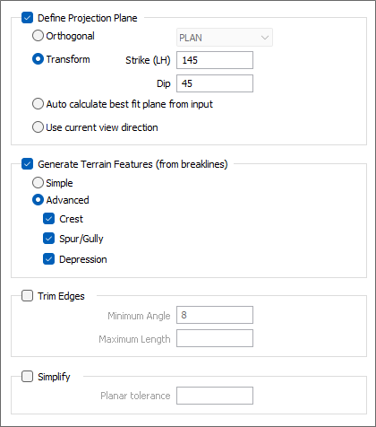
On the Options tab of the DTM Create form you can set options to determine how the projection plane is defined, how flat facets are minimised, and how the edges of the Output wireframe are trimmed.
Define Projection Plane
Specify an Orthogonal (LOOKING WEST, LOOKING NORTH, PLAN) or Transform projection plane that will be used to define the direction in which the clipping string or outline will be stretched to create an open surface.
If you select the Transform option, enter the Strike and Dip values that will be used to calculate the transformation.
Auto calculate best fit plane from input
Select this option to calculate the best plane of fit from the active (input) layer in Vizex.
Use current view direction
Select this option to use the current view direction as the projection plane of the wireframe.
Generate Terrain Features (from breaklines)
These options require strings (which should be contour stings) as input.
Simple
This option is enabled by default. When strings are triangulated as contours, the connection of any contour string back onto itself is avoided. Instead, a connection to the next contour string is chosen. If the Simple option is disabled, a string may be connected back onto itself to create a flatter facet.
You may want to disable this option if you are creating a DTM from a pit design that includes a road.
Advanced
Select this option to generate advanced (crest, spur/gully or depression) terrain features.
Example: Generate Spurs
Trim Edges
Select this option to trim the edges of the DTM where those edges are over-length or have narrow angles.
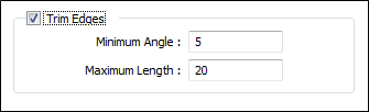
You can choose one or both of the following options:
Minimum Angle
The edges of the triangulation which are less than the specified Minimum angle are deemed invalid and are trimmed.
Maximum Length
The edges of the triangulation which are longer than the specified Maximum length are deemed invalid and are trimmed.
Since the trimming process will not trim over lines and will only trim into points, you can add additional lines to the input data to limit the effects of over-aggressive trimming. These "trim lines" should not be confused with the input "restriction strings" that can be used to limit the extent of the DTM.
Simplify
Select the option to enable entry of a planar decimate tolerance.
Planar Decimate Tolerance
This option allows you to better manage DTM creation from very large data sets, such as LiDAR.
The value entered (in grid units) is the maximum amount that the triangulation is allowed to move in any direction after vertices are removed. If no planar tolerance is specified, a default value of 0.01 will be applied automatically. Specifying a large planar tolerance will significantly alter the nature of the triangulation.
See: Trim Edges