Stope Optimisations
When considered in cross-section relative to the direction of stoping, some stoping methods require the stopes to be generated within the constraints of a regular grid pattern or framework. Advance supports this by allowing you to specify the cross-sectional design requirements relative to a two-dimensional grid pattern, along with the position and orientation of that grid relative to the target ore body. It then projects “tubes” from the cells of the grid into the ore body and cuts these tubes into thin slices, for which the economic values are determined.
The quantities and starting locations for the tubes are defined by the framework. The framework may be oriented with respect to the target block model as required to ensure that the stopes are generated in the appropriate direction, which will be orthogonal to the plane of the tubing grid and is referred to as the "strike" of the stopes. (This may be different to the geological strike of the ore body.) The cross-sections of the stopes are predetermined by the spacing and inclination of the lines in the framework.
Using the along-strike design minimum and maximum stope lengths, separation, and near and far dilution lengths specified on the Presets tab, the mathematical programming solver recombines the slices to form stopes that satisfy the specified value or grade requirements optimally.
Setup Stope Optimisations
![]()
Frameworks
Stope Optimisation is run over a “framework” of tubes and slices. This defines the parameters of the optimisation, such as the location, rotation, height, length, default dip and strike of the stopes.
You can create and select multiple frameworks to view the different areas of the ore body you want to run the optimisation on.
Add New Framework
To add a framework:
-
In the Frameworks panel, right-click on the Stope Optimiser Frameworks node and select Add > New Framework.
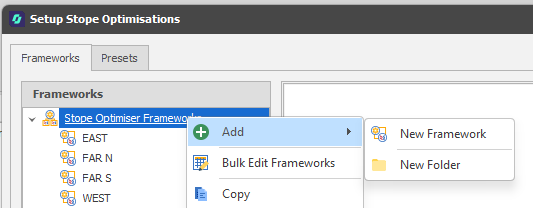
You can also right-click and select Add > New Folder. Use the mouse to drag and drop selected frameworks into a folder.
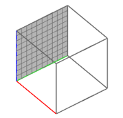
A default (100 by 100) 3D framework box is added in the embedded Design Window.
-
In the embedded Design panel, load the Block Model associated with the framework.
-
In the Properties panel, select the Block Model associated with the framework.
Note: If you cannot see the framework/block model, its spatial location may lie beyond the current display limits (particularly when other layers are already loaded).
To zoom to the extents of the block model, select Zoom to Data Extents via the Quick Access (Design Panel Commands) toolbar:
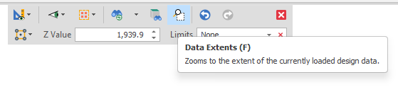
-
Rotate the display and use the mouse to select an area of the ore body that has the same Strike.
-
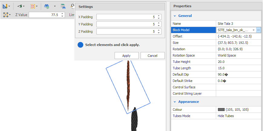
Click on the ellipsis alongside Block Model in the Properties panel.
The framework box is positioned over the selected portion of the ore body and a Settings box is shown which allows you to specify X, Y and Z padding values to expand the extents of the framework. This will update the Size and Offsets of the framework in the Properties panel (see below).
-
Right-click or click Apply.
-
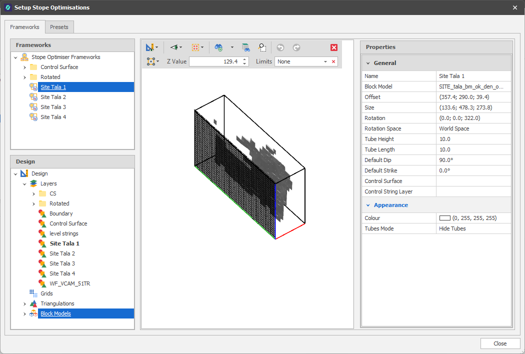
In the Properties panel, set further framework/stope tube properties to determine how the stope “tubes” will be projected from the cells of the framework into the ore body:
Properties
Block Model
Use the drop-down to select/refresh the Block Model associated with the framework.
Click on the ellipsis to interactively adjust the extents of the framework based on the block model or a selected portion of the block model.
Offset
Offset X, Y, Z: Offsets the framework along the X-axis, Y-axis and X-axis from the centre of the block model framework, respectively. Defaults: 0
Rotation
To ensure that the tubes are perpendicular to the orebody, in the Properties panel, click the ellipsis alongside Rotation.
This puts the Design Window into Rotation mode and a prompt at the top right of the display prompts you to select the strike vector.
Interactively click and drag the mouse to see a preview of the rotation of the framework box:
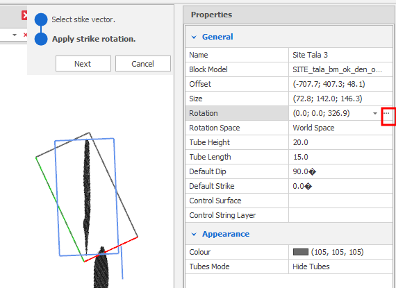
Click Next to apply the strike rotation to the framework box.
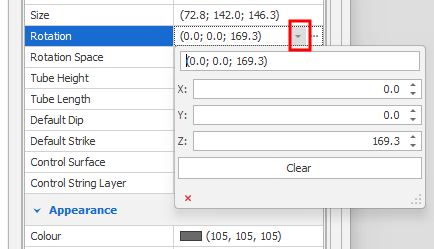
You can also enter or modify the strike rotation value in the Rotation box in the Properties panel.
Rotation X, Y, Z: Rotates the framework around the X-axis, Y-axis and X-axis, respectively. Applies a degree offset to the block model frameworks rotation. Defaults: 0
Rotation Space
Choose between "world space" rotation (the default) or "block model space" rotation.
-
In "world space" a rotation of 0,0,0 will always face East and be flat in the X-Y plane.
-
In "block model space" a rotation of 0,0,0 will have the same rotation as your block model, so if your block model is tilted, your framework will also be tilted.
World space is recommended unless you have a particular use case for using block model space.
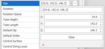
Size
To extend the size of the framework box you can click the ellipsis alongside Size in the Properties panel and use the mouse to extend the sides of the framework box:
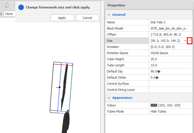
As you click and drag the side of the box, the extended side is previewed in blue. Right-click or click Apply.
You can then enter or modify the X. Y, Z values in the Size box in the Properties panel.
Size X, Y, Z: Defines the Width, Depth and Height of the framework, respectively. Defaults: 0
Tube Height/Tube Length
Use the spin controls to adjust the Height and Length of the stope tubes. Defaults: 10
Default Dip
Enter (or use the spin controls to adjust) the angle (0 <= x <= 90°, positive downwards) at which the stopes dip, relative to the horizontal plane. default: 90°
Default Strike
Enter (or use the spin controls to adjust) the Strike of the stope tubes. Strike is the bearing (0° to 360° measured clockwise from North) of the line that is formed by the intersection of the plane of the stope tubes with a horizontal surface. Default: 0°
You can set common Stope properties (Height, Length, Dip, Strike, etc.) for all selected frameworks simultaneously.
In the Frameworks panel, click the Stope Optimiser Frameworks node to select ALL frameworks. Alternatively, hold down the SHIFT key or the CTRL key as you click to select frameworks with the mouse.
Control Surface/Control String
Select a triangulated surface or string layer to inform the Dip/Strike of the tubes, where the tubes get their strikes by registering to the control surface or strings. If the triangulation or control strings are not defined for a tube, or the triangulation/strings fall outside of constraint ranges, a tube will revert to the default Dip/Strike.
Appearance
Colour
Click on the Colour patch to select a display colour for the framework (grid lines and cells). The same colour is also applied to the stope tube lines and the tube mesh, when shown (see below).
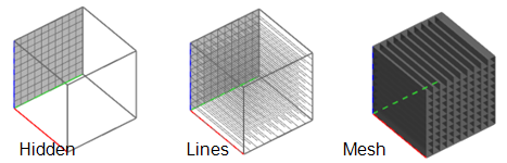
Tubes Mode
Once the framework is positioned over the ore body, you can choose whether to hide or show the stope “tubes” that are projected from the cells of the framework grid and into the ore body.
If you choose to show the tubes, you can either Show Tube Lines or Show Tube Mesh:
Presets are a collection of settings associated with a framework, which include a number of spatial and numeric mining constraints that are applied when the optimisation is run.
For more information, see: