Presets
Presets are a collection of settings associated with a framework, which include a number of spatial and numeric mining constraints that are applied when the optimisation is run.
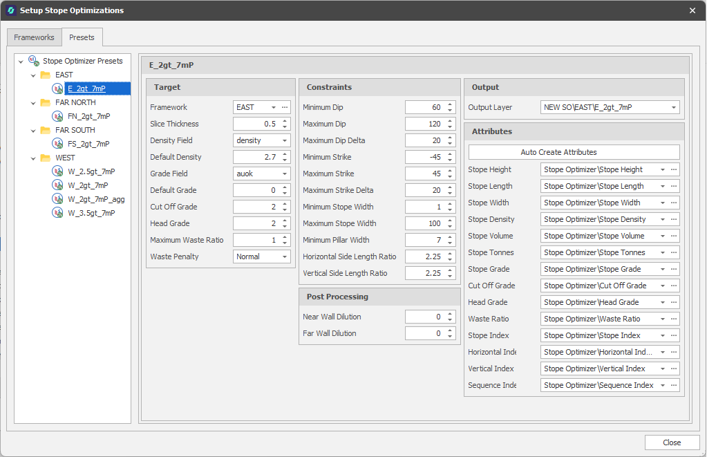
On the Presets tab of the Stope Optimisations Setup window, the parameters for optimisation can be set for each of the Frameworks you have created. Presets are selected when you select Run Stope Optimiser (on the Triangulation tab, in the Add group).
To add a preset:
-
In the Frameworks panel, right-click the Stope Optimiser Presets node and select Add > New Preset.

You can also right-click and select Add > New Folder. Typically, you will do this to group presets (for example presets with different Cutoff grades) under each of the frameworks you have created. For example, you right-click on an EAST framework folder and select Add > New Preset, then set the framework property of that preset to EAST.
To use the same presets across multiple frameworks, simply Copy and Paste a preset between folders and then rename and reset the framework property (and other parameters) accordingly.
-
Set the following parameters:
Stope Optimisation > Presets tab
Target
Framework
Select a framework as the target for optimisation. Stope Optimisation is run over a “framework” of tubes and slices. This defines the parameters of the optimisation, such as the location, rotation, height, length, default dip and strike of the stopes.
Slice Thickness
Specify the width (> 0.0) of the interval, orthogonal to the face plane of the framework along the strike of the stopes, at which the extruded tubes are sliced and populated with attributes of interest from the block model. Default: 1
Density Field
Use the drop-down to select a Density field in the block model file. If you specify a Density field, the function will calculate and enter the density of each continuous interval in the output file.
Default Density
Enter (or use the spin controls to adjust) a Default Density value. The Default Density will be used when a Density value is missing in the record being processed. If there is no Density field in the block model file, and you don't enter the default Density a value of 1.0 will be used in the calculations.
Grade Field
Use the drop-down to select a Grade field in the block model file. This is the field from which the optimisation value for each block will be sourced.
Default Grade
Enter (or use the spin controls to adjust) a Default Grade value. The Default Grade will be used when a Grade value is missing in the record being processed.
Cut Off Grade
Defines the minimum grade for blocks to be included in the stope without being considered waste. Default: 2
Head Grade
Defines the required overall grade of a stope to be accepted. Default: 2
Maximum Waste
Specify the grade above which material is considered to be ore.
Waste Penalty
Choose the (Normal, Prioritise metal, Prioritise Grade) Waste Penalty . Normal is the default and provides the most optimal result.
Constraints
In the Constraints group, specify the dimensions, minimum separations and inclinations in each direction for the stopes.
The values specified for dimensions, including those for dilution, and separations should be multiples of the Slice Thickness you have specified in the Target group. The values will be divided by the Slice Thickness value and rounded as required to produce a whole number of slices.
Using a right-handed coordinate system, which may be rotated with respect to the real-world coordinate system, the table below describes how to identify each of the directions:
|
Group |
Right-handed Coordinate Axis |
Description |
|---|---|---|
|
Along Strike |
Y |
Along the length of the extruded tubes, perpendicular to the face plane of the framework. The tubes are sliced, parallel to the face plane of the framework, in this direction. |
|
Across Strike |
X |
Across the width of the extruded tubes, parallel to the face plane of the framework. |
|
Vertical |
Z |
Towards the height of the extruded tubes, parallel to the face plane of the framework. |
Minimum and Maximum Dip
Set the Minimum and Maximum allowable Dip angle. Defaults: 60° and 120°, respectively.
Maximum Dip Delta
Limits the change in dip between the left and right side of the same stope face. Default: 20°
Minimum and Maximum Strike
Set the Minimum and Maximum allowable strike angle. . Defaults: -20° and 120°, respectively.
Maximum Strike Delta
Limits the change in strike between the top and bottom side of the same stope face. Default: 10°
Minimum and Maximum Stope Width
Define the smallest and largest allowable width for a stope. Defaults: 5 and 100, respectively.
Minimum Pillar Width
Defines the smallest allowable pillar width. Default: 10
Horizontal Side Length Ratio
Controls the maximum ratio of length between the two edges on the top/bottom of the stope going along the width. Stops the stopes from becoming too “triangular” in shape. Default: 2.25
Vertical Side Length Ratio
Controls the maximum ratio of length between the two edges on the left/right of the stope going along the width. Stops the stopes from becoming too “triangular” in shape. Default: 2.25
Post Processing
In the Post Processing group, specify the parameters for any dilution to be included.
Near Wall Dilution
(Optional.) Specify the dilution to be included at the near end of the stopes (closest to the face plane of the framework.
Far Wall Dilution
(Optional.) Specify the dilution to be included at the far end of the stopes (furthest from the face plane of the framework).
Output
Use the drop-down to select an Output Layer.
Tip: In the Layer Selection pane, you can right-click on the Layers node (or a folder) to Add a new layer.
Stope solids, generated using the framework and its presets, are added to the layer.
Attributes
Specify the layer attributes that will be populated with the results from the optimisation. Initially, you may prefer to click the Auto Create Attributes button to auto-create them.
Attributes include Stope dimensions and the Grade and Tonnage attributes that the interrogation writes the optimisation grade and total tonnes to. Cut Off Grade and Head Grade attributes are also stored. Cutoff Grade: Defines the minimum grade for blocks to be included in the stope without being considered waste. Head Grade: Defines the required overall grade of a stope to be accepted.
The Stope Index is a unique identifier assigned to each stope solid. Horizontal Index, Vertical Index, Sequence Index attributes are created which allow you to apply offsets and sequence the stopes as part of scheduling.