Extrude Tunnels
![]()
Tunnel geometry is generated from centreline, profile, and cut information. Profile and cut information can be defined by the attributes of the input centrelines, from existing tunnels, or by specifying tunnel information in the Extrude Tunnels dialog.
Input Source
Select the Source of the data that will be used as input to the function:
| Selection | Design elements you have interactively selected in the Design Window. |
| Visible | Design elements that are visible in the loaded layer. Elements that have been specifically hidden are excluded. This a quick way of selecting all visible elements in a layer without having to explicitly select them. |
| Layer | One or more layers that you select. Names of layers currently loaded in the Design Window are shown in bold. |
For large datasets, you may prefer to select a layer rather than load that layer and select all of the elements in the layer. Selecting a non-applicable layer will have no effect. In most cases, an error icon ![]() will indicate the chosen input layer is not valid. Hover over the icon to view a validation hint.
will indicate the chosen input layer is not valid. Hover over the icon to view a validation hint.
Settings
Mode
Choose a (Tunnel Info or Individual Components) Extrusion Mode. The Mode you choose will determine the Inputs that are required to be specified in the dialog.
Select this mode to extrude tunnels using existing Tunnel Information.
Use Tunnel Info Attribute
Select this check box to use the Tunnel Info Attributes of the Input Centrelines to extrude the tunnels.
Select the Tunnel Info Attribute Field that will be used to determine the (Profile, Orientation, Cut Mode, Cut Distance, Cut Threshold, and Cut Equal Parts) attributes of each tunnel.
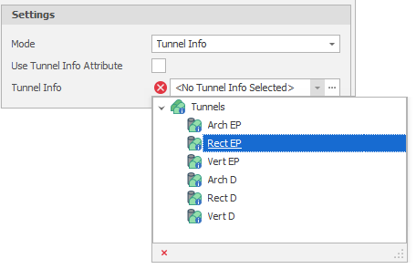
Tunnel Info
Alternatively, if Tunnels have already been setup (in Setup Tunnels & Profiles), use the drop-down list to select the Tunnel Information of an existing tunnel:
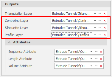
Outputs
Use the drop-downs or click on the ellipses to select one or more Output Layers.
Tip: You can right-click on a folder in the Layer Selection pane to Add a new layer.
Tunnels will be saved to the specified Triangulation layer. Output attributes of the extruded tunnels are Sequence, Length, and Volume.
 Click the Delete icon to clear one or more layer or attribute selections.
Additional Outputs
Note: You also have the option of outputting other extruded tunnel geometry into different layers. These additional outputs are Cut Centrelines, Projected Profiles, and Silhouette Polygons.
In this example, singular Tunnel Information has been used to extrude tunnels and the specified attributes have been written to a single Triangulation layer:
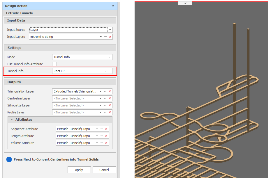
Extrude Tunnels: Tunnel Information (Singular Tunnel Info)
In this example, variable Tunnel Information Attributes of the Input Centreline Layer has been used to extrude tunnels and the specified attributes have been written to a single Triangulation layer:
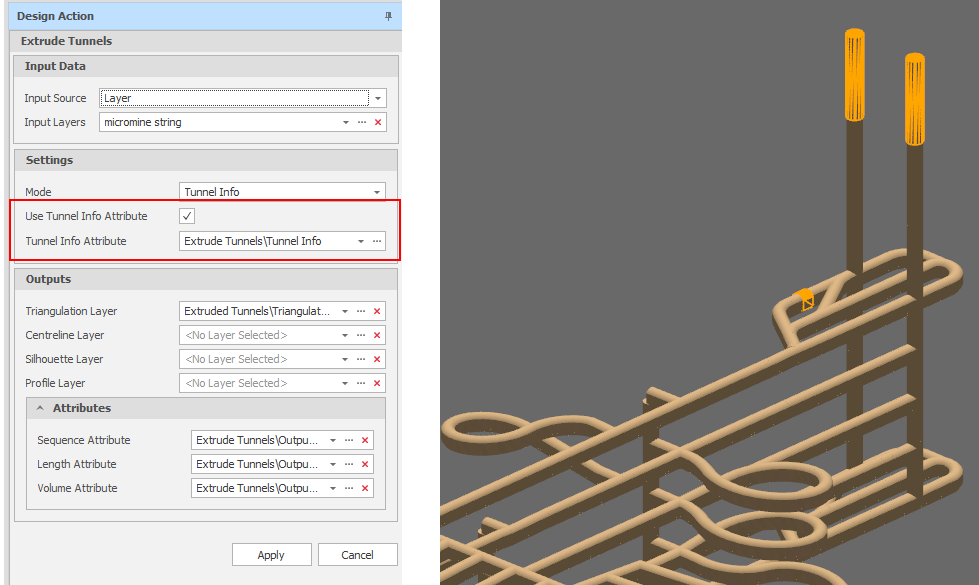
Extrude Tunnels: Tunnel Information (by Centreline Attribute)
Select this mode to extrude tunnels by specifying the individual (Profile, Orientation, Cut Mode, Cut Distance, Cut Threshold, and Cut Equal Parts) components of information needed to extrude the tunnels.
Use Profile Attribute
Select this check box to use the Profile Attribute of the Input Centrelines to set the profile of the tunnels.
Select the Profile Attribute Field that will be used to determine the profile of each tunnel.
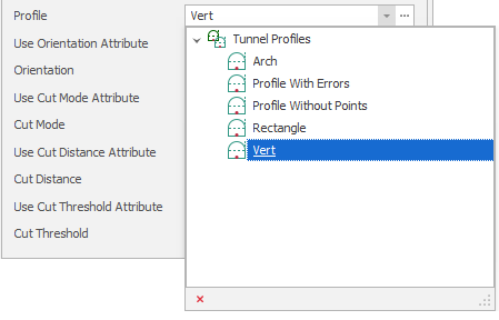
Profile
Alternatively, if Tunnels and Profiles have already been setup (in Setup Tunnels & Profiles), use the drop-down list to select a Tunnel Profile:
Use Orientation Attribute
Select this check box to use the Orientation Attribute of the Input Centrelines to set the orientation of the tunnels.
Select the Orientation Attribute Field that will be used to determine the orientation of each tunnel.
Orientation
Alternatively, use the drop-down list to select an Orientation:
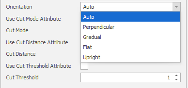
| Orientation | Description |
|---|---|
| Auto |
The most appropriate profile orientation is chosen based on centreline gradient, direction and cut settings. This is the default option and is the best option for most non-vertical centrelines. Auto will work for purely vertical tunnels but may fail on tunnels that have a mixture of purely vertical segments and segments that are not vertical. |
| Perpendicular |
A profile orientation which is perpendicular to the centreline direction (bearing and grade). Centrelines that change directions have profiles facing a direction based on the previous and next segments. |
| Gradual |
Like Perpendicular except that the profile orientation gradually transitions from the previous to the next orientation for cut segments. |
| Flat |
The profile is always flat on the XY axis. This is the orientation to use for tunnels that are intended to be vertical. |
| Upright |
The profile is always facing directly up with a rotation based on the centrelines bearing. |
Use Cut Mode Attribute
Select this check box to use the Cut Mode Attribute of the Input Centrelines to set the cut mode of the tunnels.
Select the Cut Mode Attribute Field that will be used to determine the cut mode of each tunnel.
Cut Mode
Alternatively, use the drop-down list to select a Cut Mode:
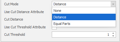
| Mode | Description |
|---|---|
| None | Choose this for an access tunnel or shaft which is non-productive. |
| Distance | Material is cut by a specified Cut Distance. |
| Equal Parts | Material is cut in a specified a number of Equal Parts. |
Use Cut Distance Attribute
Select this check box to use the Cut Distance Attribute of the Input Centrelines to set the cut distance of the tunnels.
Select the Cut Distance Attribute Field that will be used to determine the cut distance of each tunnel.
Cut Distance
Alternatively, enter or use the spin controls to set a Cut Distance (in metres).
Use Cut Threshold Attribute
Select this check box to use the Cut Threshold Attribute of the Input Centrelines to set the cut threshold of the tunnels.
Select the Cut Threshold Attribute Field that will be used to determine the cut threshold of each tunnel.
Cut Threshold
Alternatively, enter or use the spin controls to set a cut threshold (in metres). If the length of the final cut of a tunnel is less than the Cut Threshold, the cut segment is combined with the previous segment.
Use Cut Equal Parts Attribute
When the Cut Mode (above) is Equal Parts, select this check box to use the Cut Equal Parts Attribute of the Input Centrelines to set the cut equal parts value for the tunnels.
Select the Cut Equal Parts Attribute Field that will be used to determine the cut equal parts value for each tunnel.
Cut Equal Parts
Alternatively, when the Cut Mode (above) is Equal Parts, enter or use the spin controls to set a cut equal parts value.
Outputs
Use the drop-downs or click on the ellipses to select one or more Output Layers.
Tip: You can right-click on a folder in the Layer Selection pane to Add a new layer.
Tunnels will be saved to the specified Triangulation layer. Output attributes of the extruded tunnels are Sequence, Length, and Volume.
Click the Delete icon to clear one or more layer or attribute selections.
Additional Outputs
Note: You also have the option of outputting other extruded tunnel geometry into different layers. These additional outputs are Cut Centrelines, Projected Profiles, and Silhouette Polygons.
In this example, individual Tunnel Information components specified in the dialog have been used to extrude the tunnels and the specified attributes have been written to a single Triangulation layer:
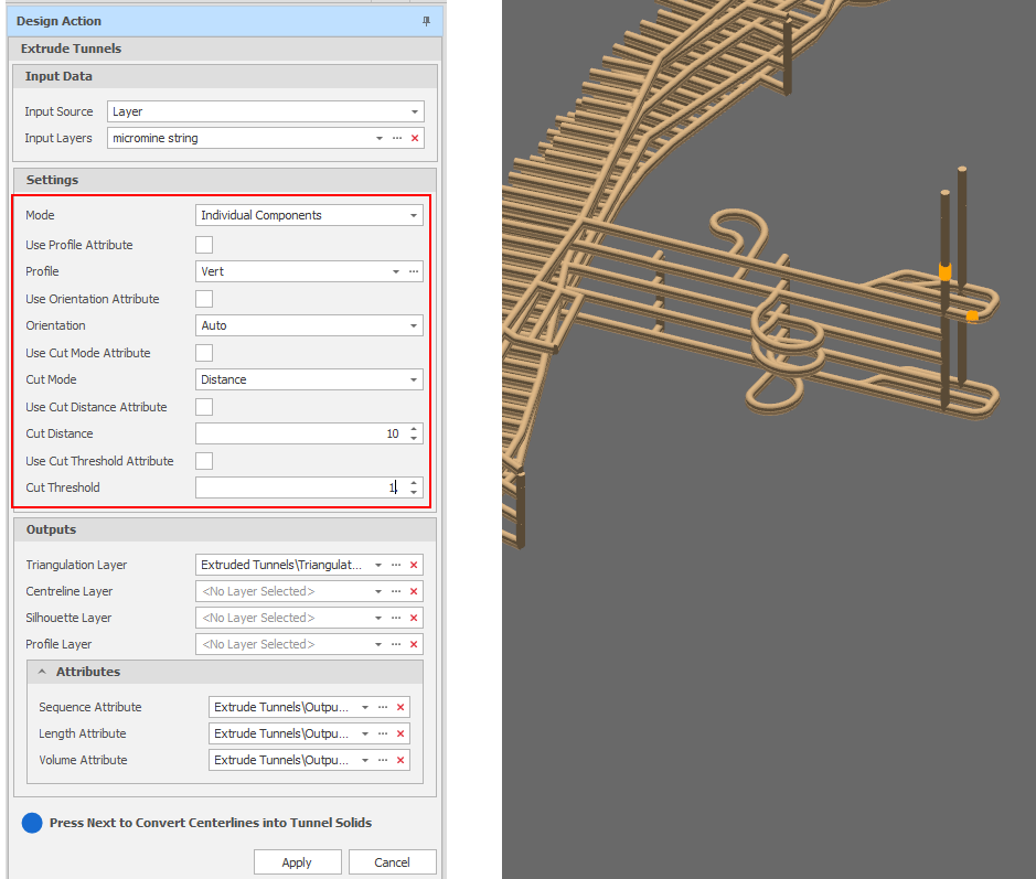
Extrude Tunnels: Individual Components (Specified in the dialog)
In this example, variable Tunnel Information Attributes of the Input Centreline Layer has been used to extrude tunnels and the specified attributes have been written to a single Triangulation layer:
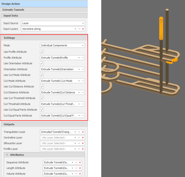
Extrude Tunnels: Individual Components (by Centreline Attribute)
Note that choosing components singularly or by attribute is optional for each component, so some tunnel properties could be defined by attribute, while others could be defined singularly in the dialog.
Apply
Click Apply to convert the centrelines into Tunnel Solids (or click Cancel to abandon the action).