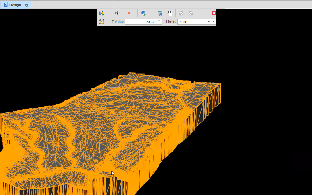
Extrude Surface
![]()
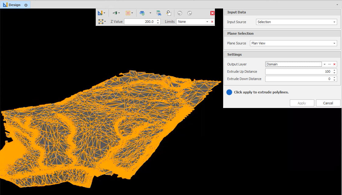
Input Source
Select the Source of the data that will be used as input to the function:
| Selection | Design elements you have interactively selected in the Design Window. |
| Visible | Design elements that are visible in the loaded layer. Elements that have been specifically hidden are excluded. This a quick way of selecting all visible elements in a layer without having to explicitly select them. |
| Layer | One or more layers that you select. Names of layers currently loaded in the Design Window are shown in bold. |
For large datasets, you may prefer to select a layer rather than load that layer and select all of the elements in the layer. Selecting a non-applicable layer will have no effect. In most cases, an error icon ![]() will indicate the chosen input layer is not valid. Hover over the icon to view a validation hint.
will indicate the chosen input layer is not valid. Hover over the icon to view a validation hint.
Plane Source
Choose a screen plane. Note that this will be used as the plane of the extrusion.
| Plan | Use Plan View (looking top down). |
| Camera | Use the current Camera view. |
* The current plane of the view in the Design Window is not changed.
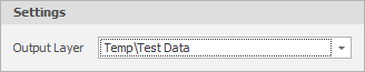
Output Layer
Use the drop-down to select an Output Layer.
Tip: In the Layer Selection pane, you can right-click on the Layers node (or a folder) to Add a new layer.
Extrude Up/Down Distance
You can choose to Extrude Up, Down, or in both directions, by a specified Distance in the chosen plane (Plan View or Camera).
Extruding in Plan View will produce an orthogonal extrusion: