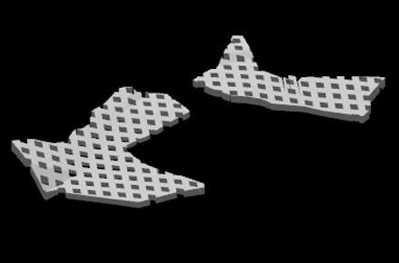
Extrude Shapes to Surface
![]()
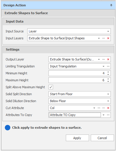
Extrude Shapes to Surface Design Action
Input Source
Use one of the following methods to select the input shapes to be extruded.
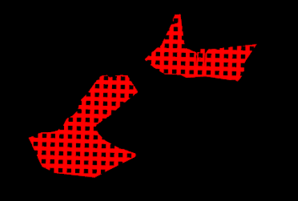
Select the Source of the data that will be used as input to the function:
| Selection | Design elements you have interactively selected in the Design Window. |
| Visible | Design elements that are visible in the loaded layer. Elements that have been specifically hidden are excluded. This a quick way of selecting all visible elements in a layer without having to explicitly select them. |
| Layer | One or more layers that you select. Names of layers currently loaded in the Design Window are shown in bold. |
For large datasets, you may prefer to select a layer rather than load that layer and select all of the elements in the layer. Selecting a non-applicable layer will have no effect. In most cases, an error icon ![]() will indicate the chosen input layer is not valid. Hover over the icon to view a validation hint.
will indicate the chosen input layer is not valid. Hover over the icon to view a validation hint.
Settings
Output Layer
Use the drop-down to select an Output Layer.
Tip: In the Layer Selection pane, you can right-click on the Layers node (or a folder) to Add a new layer.
Attributes of the input shapes will be copied to the output layer triangulation.
Limiting Triangulation
Use the drop-down to select the target orebody. The geometric configuration of the triangulation you select will typically comprise of several flat-lying seam or stratiform deposits which are relatively shallow.
Minimum and Maximum Height
The Height values you enter here will determine the allowable height of the rooms and pillars.
Split Above Maximum Height
Select this check box to split orebodies greater than the specified Maximum Height value. Orebodies greater than 6 metres in height (the default Maximum Height value) are typically worked in multiple passes, which means they need to be split.
Solid Split Direction
If you have selected the Split Above Maximum Height check box, choose the (Start From Floor, Start From Roof) direction in which the orebody will be split.
Solid Dilution Direction
Choose the (Below Floor, Above Roof) direction and extent of dilution.
Dilution typically occurs horizontally and vertically into the surrounding waste rock due to over-excavation during drilling and blasting or, in the case of room and pillar mining, from the failure of roof and pillars. The direction and extent of dilution are influenced by factors such as pillar geometry, blast design, drilling accuracy and rock mass quality.
Cut Attribute
This attribute stores the sequence of the cuts that will be made when extracting ore.
Apply
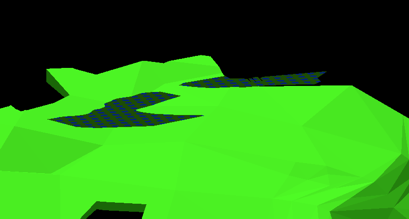
Click Apply to extrude the shapes.
Open the Output layer to view the results of the process.