Create Surface
![]()
Do the following:
-
Select the Source of the data that will be used as input to the function:
Selection Design elements you have interactively selected in the Design Window. Visible Design elements that are visible in the loaded layer. Elements that have been specifically hidden are excluded. This a quick way of selecting all visible elements in a layer without having to explicitly select them. Layer One or more layers that you select. Names of layers currently loaded in the Design Window are shown in bold. For large datasets, you may prefer to select a layer rather than load that layer and select all of the elements in the layer. Selecting a non-applicable layer will have no effect. In most cases, an error icon
 will indicate the chosen input layer is not valid. Hover over the icon to view a validation hint.
-
(Optional) You may need to change the screen plane to be able to select all of the design elements you want to triangulate.
Plan Use Plan View (looking top down). Camera Use the current Camera view. * The current plane of the view in the Design Window is not changed.
-
Choose whether to create a boundary around the triangulation. If a boundary is created, it can be Included or Excluded from the triangulation.
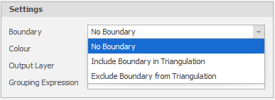
If a boundary is excluded from the triangulation, then the boundary is only used to define the extents of the triangulation. Only those portions of the selected shapes that are enclosed by the boundary are triangulated.
If a boundary is included in the triangulation, then the boundary that encloses all the selected shapes is also triangulated.
-
Click on the Colour cell to choose between theme colours, standard colours or select a colour from a chosen palette.
-
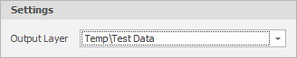
Use the drop-down to select an Output Layer.
Tip: In the Layer Selection pane, you can right-click on the Layers node (or a folder) to Add a new layer.
-
Click on the ellipsis to use the Expression Editor to create a Grouping Expression that will be used to subdivide the input source data into groups. The action will be applied to each group, rather than to the input source as a whole.
For example, you want to apply an action to Stope Solids:
GetText(IdentifiersStope)
-
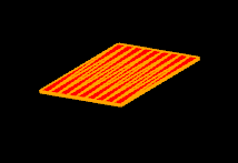
Click Apply to triangulate the selected shapes.

The selected polylines are triangulated: