Contour
When generating volumes, qualities and reserves, having accurate detailed Solids is an important part of the process. However, most of the time you're using your Solids as a visual aid where the high level of detail is usually unnecessary.
To contour triangulations in your Design Data, right-click on the Triangulation node or any triangulation and select Contour.
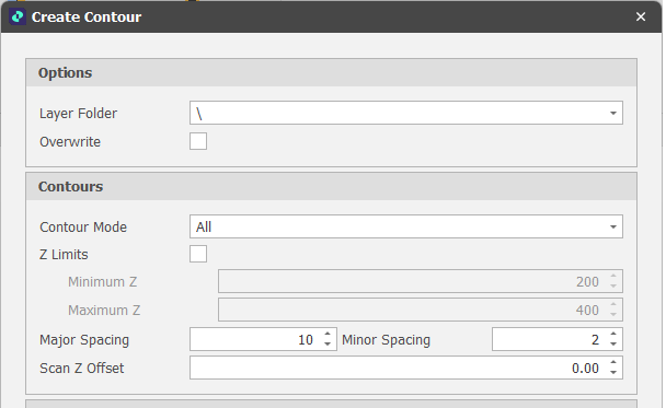
Options
Layer Folder
The Layers (root) folder in the Design Data pane is selected by default. Use the drop-down to select a destination folder
Overwrite
Choose whether to overwrite the existing Triangulation or create a new simplified Triangulation.
Similar to Solid Simplification, the Recommended Process is to not overwrite at first, but to create "_Contoured" clones until you are happy with the result. To reduce the size of your model once completed, the recommended process is to export your original Triangulation, delete it in your model and then run "Compact Database" in your back-end Database Maintenance settings.
Contours
Contour Mode
Choose a Contour Mode:
All contour mode: Major and minor contour lines are used to represent the solids. Major contours are typically thicker, and are often labelled with their elevation value, while minor contours are lighter and thinner, and usually do not have labels.
Z Limits
Optionally, select this check box to set the Minimum Z and Maximum Z Limits of the contour line segments.
Major/Minor Spacings
Use the drop-downs to select the spacing between Major and Minor contour lines.
Scan Z Offset
Optionally, set the offset to be applied when contouring by Z value.
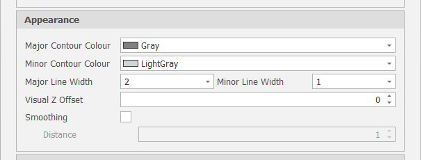
Appearance
Major/Minor Contour Colours
Use the drop-downs to select a colour for the Major and Minor contour lines.
Major/Minor Line Widths
Use the drop-downs to select a line width for the Major and Minor contour lines.
View Z Offset
Optionally, offset the contours in the display by a specified Z value.
Smoothing
When this check box is selected, each contour will be filtered so that the minimum distance between each point is greater than or equal to the set Distance.
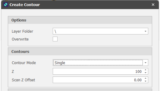
Single contour mode: A single contour is generated using the specified Z value.
Z
Use the spin controls to set an elevation (Z) value for the contour line segment.
Scan Z Offset
Optionally, set the offset to be applied when contouring by Z value.
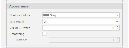
Appearance
Contour Colour
Use the drop-down to select a colour for the contour lines.
Line Width
Use the drop-down to select a line width for the contour lines.
View Z Offset
Optionally, offset the contours in the display by a specified Z value.
Smoothing
When this check box is selected, each contour will be filtered so that the minimum distance between each point is greater than or equal to the set Distance.
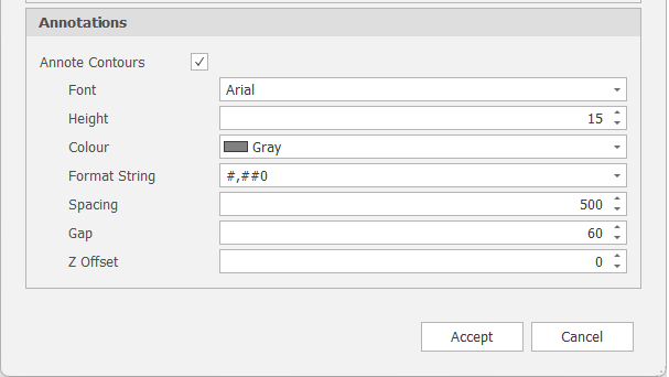
Annotations
Annotate Contours
Select this check box to display annotations on contours, set font characteristics, a text format string, annotation colour, gap and Z offset values, etc.
Accept
Click Accept to apply the contouring settings you have specified (or Cancel).
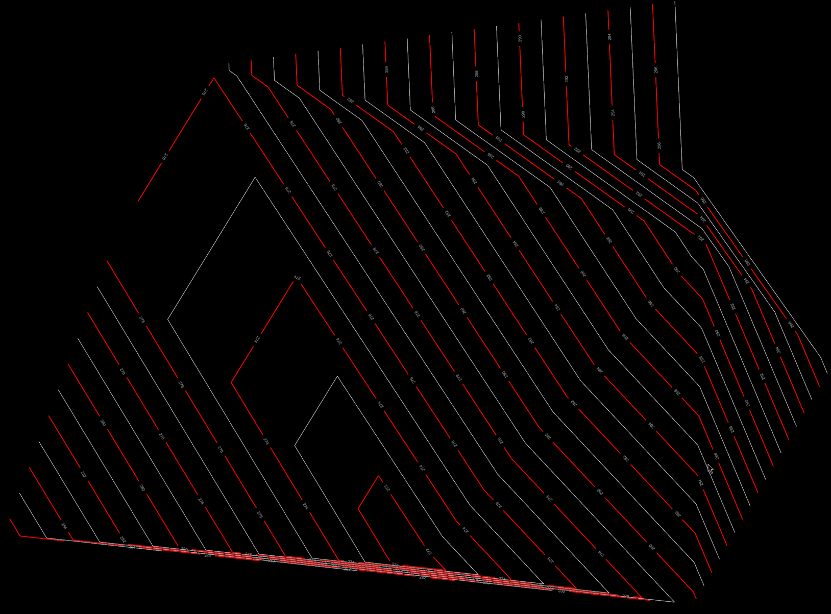
A contoured solid with Major and Minor contours.