Области проектирования
Установите флажок Использовать несколько областей проектирования выемок, чтобы задать параметры до 10 областей проектирования. Затем вы можете выбрать способ определения границ этих областей.
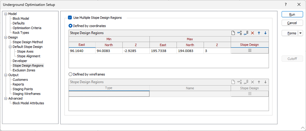
Определяется координатами
Выберите этот параметр, чтобы обозначить области, для которых применяются различные параметры проектирования выемок, указав диапазоны координатных значений.
Мин Вост Коорд
(Только для минимальных/максимальных координат.) Укажите восточную координату нижней границы области.
Мин Сев Коорд
(Только для минимальных/максимальных координат.) Укажите северную координату нижней границы области.
Мин Z
(Только для минимальных/максимальных координат.) Укажите вертикальную координату нижней границы области.
Макс Вост Коорд
(Только для минимальных/максимальных координат.) Укажите восточную координату верхней границы области.
Макс Сев Коорд
(Только для минимальных/максимальных координат.) Укажите северную координату верхней границы области.
Max Z
(Только для минимальных/максимальных координат.) Укажите координату по высоте (Z) для верхней границы области.
Проектирование выемочных единиц
Select the form set that specifies the axes and the alignment of the stopes and optionally edit those parameters interactively. See: Default Stope Design & Stope Alignment
Используйте кнопки на локальной панели инструментов для Управлять строками в списке.
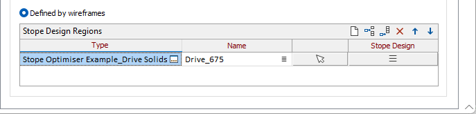
Определено каркасами
Тип/Имя каркаса
Выберите каркас с указанными типом и именем, чтобы задать каждую область выемки. Используйте кнопки на панели инструментов для Управлять строками в списке. For each wireframe you add to the grid, you can specify a Name. Вы также можете использовать кнопку Выбрать из Визекса (или выбрать пункт контекстного меню), чтобы свернуть форму и интерактивно выбрать нужный каркас для вставки и возврата в форму.
Проектирование выемочных единиц
Select the form set that specifies the axes and the alignment of the stopes and optionally edit those parameters interactively. See: Default Stope Design & Stope Alignment