Output
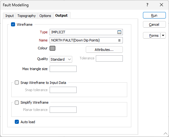
On the Output tab of the Fault Modelling form, you can write the implicit model to an output file and generate wireframe output.
Wireframe
To generate wireframe output, select the Wireframes check box.
Type and Name
Double-click (F3) to select the Type and Name of the output wireframe.
Colour
Double click (F3) to select the Colour that will be used to display the generated wireframe.
Attributes
Click the Attributes button to set attributes for the wireframe output.
User-defined attributes may be mapped against the fields in the Input file. It is also possible to specify a default value for each attribute. Default values are used when a corresponding value in the Input file is either missing or is not mapped.
Tolerance
Specify a tolerance (in Grid units).
Quality
This setting provides a convenient way to control the quality and the speed of wireframe generation. There are five quality settings: Draft, Standard, High, Ultra and Custom.
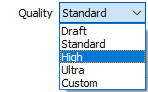
Setting the quality to Draft allows the general shape of the output wireframes to be generated quickly.
With the exception of Custom, each quality setting has a pre-set error tolerance value. The error tolerance for Draft is approximately twice that for Standard, which, in turn, is twice that for High, etc.
Setting the Quality to Custom allows a user-specified error tolerance. There is no limit to the user-specified error tolerance value (and hence the minimum mesh size), other than that imposed by available system memory.
Max triangle Size
To eliminate large meshes, specify a Maximum Triangle Size parameter in grid units.
By default, mesh size is controlled by the tolerance parameter, which specifies the maximum error between the rendered surface and the actual surface. Typically, larger meshes are used where the surface is relatively flat, and smaller meshes are used where the surface has high curvature.
If a Max Triangle Size is specified then all triangles will be that size, or smaller if they fail the tolerance test.
Snap wireframe to input data
The generated wireframes may be slightly offset from the points they were created from. Select this check box to snap the wireframes to the input data. Snapping will move the closest triangle to each snap point, if the distance between the two is less than the specified Snap tolerance.
If you do not enter a value, the default tolerance is 1 metre.
Simplify Wireframes
Select this option to reduce the number of vertices in the triangulation by eliminating those points that can be removed without causing the triangulation to move by more than the specified tolerance values:
- Planar Tolerance. This is the maximum amount that the triangulation is allowed to move in any direction after vertices are removed.
If no planar tolerance is specified, a default value of 0.01 will be applied automatically. Specifying a large planar tolerance will significantly alter the nature of the triangulation.
Auto load
Select this option to load the generated output in Vizex. The default draw style for an auto-loaded wireframe is 3D Shaded.
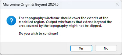
If the topograpy does not entirely cover the area covered by the bounding box, a warning prompt will appear.