Advanced Block Model Report
![]()
The purpose of the Advanced Block Model Report is to provide highly configurable reporting of block models:
-
with selectable inclusion of volume, density and mass;
-
with grades and quantities for selected attributes;
-
within spatial constraints, such as elevations, surfaces, solids and polygons;
-
by materials;
-
within wireframe solids; and,
-
grouped within hierarchies by rows and columns based on distinct field values, sets of individual and cumulative cutoffs, labelled expressions and material bins.
To view detailed examples of Advanced Block Model Report configuration in a number of scenarios, see Examples.
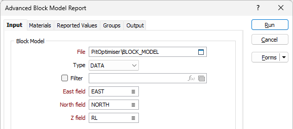
Input Block Model
The Input tab of the Advanced Block Model Report form contains options for configuring the Block model, filter and spatial constraints.
File
Double-click (or click on the Select icon) to select the name of the block model to be reported. Select the type (DATA / SURVEY / STRING / ODBC LINK / MDB LINK) of the file that contains the block model. The default file type for Block Model data is DATA.
You can also click the Pick from Vizex button to collapse the form and interactively select a layer containing the file to be inserted and return to the form.
If necessary, you can select or specify, or use an expression to define a filter to be applied to the block model based on the values of the fields within the block model. Entire blocks will be included or excluded from the report based on whether their values satisfy the criteria to pass this filter.
Note that seam block models are not supported here – they should be reported using the Stratigraphic | Seam Block Model | Report option.
East, North and Z fields
In the East, North and Z fields, enter the names of the fields that contain the easting, northing or Z (elevation) coordinates for each block in the block model. in the input file. The function uses these field names to locate the fields containing the block dimensions in the input file.
Spatial Constraint Conditions
The Spatial Constraint Conditions grid is used to configure spatial constraints (e.g. elevations, surfaces, solids and polygons) within which the block model is to be reported.
Constraints can be created using a variety of spatial objects such as DTMs, wireframes and polygons to define the reportable region of the block model. A block model is considered constrained when its centroid meets with the spatial object used to constrain it - regardless of whether all or part of the block meets the constraint.
Each Condition you add to the grid will be applied to the block model for the report. Spatial filters added to the grid will be applied in conjunction, so that only the material that falls within all of the active spatial constraints within the block model will be reported.
Use the buttons in the toolbar to Manage the rows in the list.
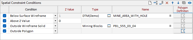
Use the Activation check box at the left of each row to enforce the spatial constraint, or deselect the check box to ignore it. This is useful for assessing the impact of individual constraints without adding and removing them from the list as required.
From the Condition drop down, select the condition that must be met for the material to be included in the report.
The following conditions can be imposed:
| Condition | Location of included Material |
|---|---|
| Below Z Value | Below Z Value Below the elevation specified in the Z Value column. |
| Above Z Value | Above Z Value Above the elevation specified in the Z Value column. |
| Below Surface Wireframe | Below the surface(s) in the wireframe type specified in Type that match the name specification in Name. |
| Above Surface Wireframe | Above Surface Wireframe Above the surface(s) in the wireframe type specified in Type that match the name specification in Name. |
| Inside Wireframe Solid | Inside Wireframe Solid Inside the solid(s) in the wireframe type specified in Type that match the name specification in Name. |
| Outside Wireframe Solid | Outside Wireframe Solid Outside the solid(s) in the wireframe type specified in Type that match the name specification in Name. |
| Inside Polygon | Inside Polygon Inside the areal extent of the polygon specified in Polygon Definition. |
| Outside Polygon | Outside the areal extent of the polygon specified in Polygon Definition. |
For Below / Above Z Value conditions, the Z Value field will be activated. Specify the elevation above or below which the material must lie.
For Below/Above Surface Wireframe and Inside/Outside Wireframe Solid conditions, the Type field is activated. Specify or select the Name of the wireframe type that contains the surface(s) below/above, or solid(s) inside/outside of, which the material must lie.
For each wireframe you add to the grid, you can select a Name. You can also use the Pick from Vizex button (or select the context menu option where available) to collapse the form and interactively select the required Wireframe to insert and return to the form.
For Inside/Outside Polygon conditions, the Polygon Definition field is activated. Click the button to specify the file that contains the polygon(s) within the areal (x, y) extents of which the block model is to be reported.
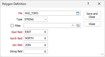
In the Polygon Definition form that opens, enter the Name and Type of the polygon file. You can also click the Pick from Vizex button to collapse the form and interactively select a layer containing the file to be inserted and return to the form. The default type for polygons is STRING.
If required, select, define or specify a Filter to be applied to the points in the file. Points will be included or excluded from the polygon(s) based on whether their values satisfy the criteria to pass this filter.
Use the East and North fields to select the easting and northing coordinates for each point in the polygon(s). Use the Join field to select the name of the field that contains the join values for the points in the polygon(s). Only the areal (x, y) extents of the polygon(s) are considered – the z-values of the points are ignored. As such, the Z field is not required.
Optionally, you can use the String field to select the name of the field that contains the string values for the points in the polygon(s).
Click OK in the Polygon Definition form to return to the Input tab.
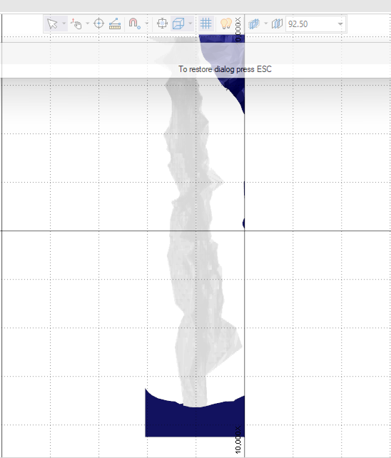
When constraints have been configured in the grid, if you click the Preview button in the toolbar to display a preview the interaction of the spatial constraints with the block model:
Forms
Click the Forms button to select and open a saved form set, or if a form set has been loaded, save the current form set.
Run
Finally, click Run to run the function. Estimates will be calculated. For very large files this can take a few moments.