Drillholes
This
Drillhole Tracker
The Drillhole Tracker tool has been added to Drillholes on the Drillhole tab, in the Planning group to enable tracking of the deviation between a planned and active drillhole.
![]()
![]()
By specifying a planned drillhole and selecting an active drillhole from a database or survey file, you can generate output showing the projection of the selected drillhole according to deviation information recorded. Adjustments made in the Tracker tab to the Drift, Lift and Over Distance values can be written or appended to the Drillhole Tracker report.
You can also modify a collar location if you use a Survey file, as well as optionally specify a wireframe containing pierce points where the drillhole intersects in order to report the distance from planned to projected holes.
For more information, see Drillhole Tracker.
Auto Load Drillhole Pattern
The Auto load option has been added to the Output tab of the Drillhole Pattern Setup form to automatically load the drillhole pattern in Vizex on creation.
The option is enabled by default. Where a Drillhole database (DHDB) is defined in the dialog, the pattern will be loaded as a Trace layer. If no DHDB has been defined, collar locations will be loaded as Points.
Insert Missing Intervals
The Missing Interval option has been added to the Repair All options on the Drillhole | Validate tab, in the Repair group to insert missing intervals into an Interval file on repair.
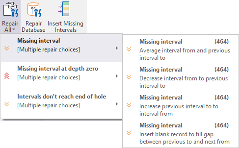
Additionally, the Insert Missing Intervals tool has been added to the Drillhole | Validate tab, in the Repair group for access when a drillhole validation report is open and a missing interval is required.
![]()
Drillhole Database Display Options
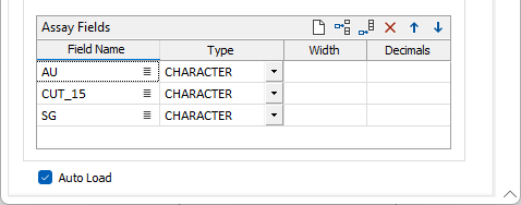
The Display Options grid has been added to the Drillhole Database New, Edit and Import tools. Using the new grid, you can configure the layers in the data to be automatically loaded in Vizex when the database is used in a tool or drag-and-dropped into your scene.
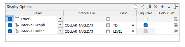
For each layer to be displayed in Vizex, you can select the associated interval file, the field to be displayed and a colour set to be used. Additionally, for Solid Trace and Interval Graph layers, you can select whether to apply a Log Scale.
When you add or change an interval file (or multiple), the Display Options are automatically filled. An Autofill button is also available in the toolbar of the Display Options grid.
Reverse Residual Adjustment
The Add residual to the first interval option has been added to the Residual Adjustment options for Downhole Compositing.
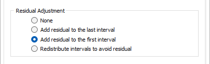
Composites which are shorter in length than the regular composites are classified as residuals. These are composites at the boundary of a domain. When dealing with residuals, users can either choose to adjust them or not. Adjustment by adding the residual to the first interval will perform downhole compositing in 'reverse' ; that is, from bottom to top. The new option is ideal for some types of ore where heavier ore settles to the bottom of an interval.
For more information, see Compositing.
Scalebar Offset Distance
The Offset distance option has been added to the Scalebar options for Drillhole graphs to offset the displayed scalebar in the downhole direction.
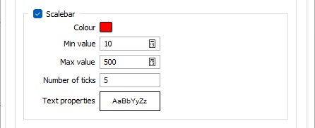
When displaying multiple drillhole graphs, scalebars overlap with each other and graphs can sometimes be offset perpendicular to the Drillhole trace to compensate. The new option provides additional support for offsetting the scalebar to improve the clarity of the plot.
For more information, see Interval Graph.