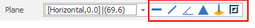
Plane
Use the tools to the right of the Plane drop-down to select a Plane Selection mode and define the plane:
-
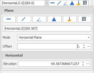
Click Horizontal on the plane selection toolbar.
-
Digitise a point to set the elevation of a horizontal plane.
-
(Optional) Use the spin controls or enter a value to Offset the plane along the normal by a set amount. A negative offset value is allowed.
The point you have digitised are used to populate a Text Edit box at the top of the Plane Selection pane.
The Text Edit box can also be used to create or edit a plane from a string. The string format shows the plane selection mode and a zero or non-zero (if specified) offset value, followed by the elevation value.
-
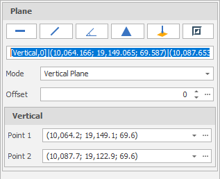
Click Vertical on the plane selection toolbar.
-
Digitise two points to define a vertical plane.
-
(Optional) Use the spin controls or enter a value to Offset the plane along the normal by a set amount. A negative offset value is allowed.
The points you have digitised are used to populate a Text Edit box at the top of the Plane Selection pane.
The Text Edit box can also be used to create a plane from a string. The string format shows the plane selection mode and a zero or non-zero (if specified) offset value, followed by the string format used for the conversion, which is “(x, y, z) | <a, b, c>“ where each lettered character can be a decimal number. (x, y, z) refers to the point of the plane. <a, b, c> refers to the vector normal of the plane.
-
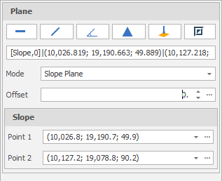
Click Slope on the plane selection toolbar.
-
Digitise two points to define a slope plane.
-
(Optional) Use the spin controls or enter a value to Offset the plane along the normal by a set amount. A negative offset value is allowed.
The points you have digitised are used to populate a Text Edit box at the top of the Plane Selection pane.
The Text Edit box can also be used to create a plane from a string. The string format shows the plane selection mode and a zero or non-zero (if specified) offset value, followed by the string format used for the conversion, which is “(x, y, z) | <a, b, c>“ where each lettered character can be a decimal number. (x, y, z) refers to the point of the plane. <a, b, c> refers to the vector normal of the plane.
-
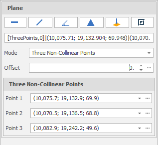
Click Three Points on the plane selection toolbar.
-
Digitise three non-collinear points to define a plane.
-
(Optional) Use the spin controls or enter a value to Offset the plane along the normal by a set amount. A negative offset value is allowed.
The points you have digitised are used to populate a Text Edit box at the top of the Plane Selection pane.
The Text Edit box can also be used to create a plane from a string. The string format shows the plane selection mode and a zero or non-zero (if specified) offset value, followed by the string format used for the conversion, which is “(x, y, z) | <a, b, c>“ where each lettered character can be a decimal number. (x, y, z) refers to the point of the plane. <a, b, c> refers to the vector normal of the plane.
-
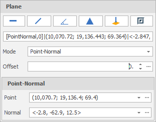
Click Point Normal on the plane selection toolbar.
-
Digitise two points that define the origin and the normal of a plane.
-
(Optional) Use the spin controls or enter a value to Offset the plane along the normal by a set amount. A negative offset value is allowed.
The points you have digitised are used to populate a Text Edit box at the top of the Plane Selection pane.
The Text Edit box can also be used to create a plane from a string. The string format shows the plane selection mode and a zero or non-zero (if specified) offset value, followed by the string format used for the conversion, which is “(x, y, z) | <a, b, c>“ where each lettered character can be a decimal number. (x, y, z) refers to the point of the plane. <a, b, c> refers to the vector normal of the plane.
To invert the currently defined plane, click Invert Plane on the plane selection toolbar.
A vertical plane is inverted by swapping the two points and the mode does not change. When a horizonal or slope plane is inverted, the mode changes to Point-Normal. This is because a horizontal or slope plane always has a normal of <0,0,1>. The inverse is a normal of <0,0,-1> and this is only possible with a point normal plane definition.
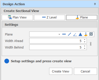
Width Ahead/Width Behind
Set the section width by specifying Width Ahead and Width Behind values. These values define the extents of a “data corridor”. In Sectional View, Ahead is a measurement taken from the section line towards you, the viewer. Behind is a measurement taken from the section line away from you.
![]() Click the Link icon to the right of the Width boxes to link or unlink the Width controls.
Click the Link icon to the right of the Width boxes to link or unlink the Width controls.
When the Width controls are unlinked you can increase or decrease the Width Ahead and Width Behind values separately to each other. This makes it possible, for example, to just view one side of the section.
To adjust Width Ahead and Width Behind values equally, simply click the icon again to link the Width controls.
A design_sectional_view_link_widths setting can also be set via All Settings and defaults to True.