Plan View
-
In the Settings dialog, choose a Selection type:
| Selection type | Description |
|---|---|
| Draw Line | Create a shape with 2 points. |
| Click the first point, move the mouse and then click a second point to define the section/clipping plane. A rubber-banded line is shown. | |
| Existing Design Element | Select a shape with 2 points. A rubber-banded line is shown. |
-
Depending on the Selection type you selected in Step 1, you will be prompted to Create or Select a shape with two points:
-
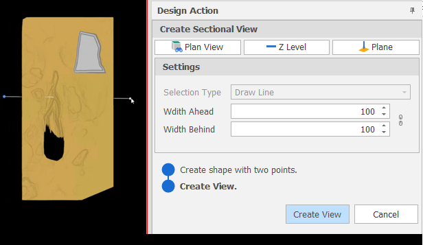
Set the section width by specifying Width Ahead and Width Behind values. These values define the extents of a “data corridor”. In Sectional View, Ahead is a measurement taken from the section line towards you, the viewer. Behind is a measurement taken from the section line away from you.
 Click the Link icon to the right of the Width boxes to link or unlink the Width controls.
When the Width controls are unlinked you can increase or decrease the Width Ahead and Width Behind values separately to each other. This makes it possible, for example, to just view one side of the section.
To adjust Width Ahead and Width Behind values equally, simply click the icon again to link the Width controls.
A design_sectional_view_link_widths setting can also be set via All Settings and defaults to True.
-
Click the Create View button:

-
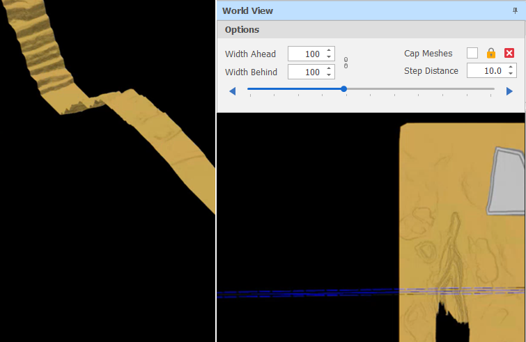
Options are provided at the top of a World View pane which is docked alongside the Sectional View.