Haulage Setup
Running haulage simulation and analysis requires both a multi-step setup and the use of haulage logic controls.
To begin simulating haulage, select the Haulage Simulation check box on the General tab of the Scenario Settings form:
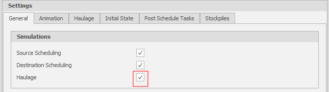
-
On the Home tab, in the Setup group: Select More > Segment Codes to add one or more Segment Codes.
During haulage, rolling resistance is controlled and speed limits are set by Segment Codes which get applied to each segment along a haul profile.
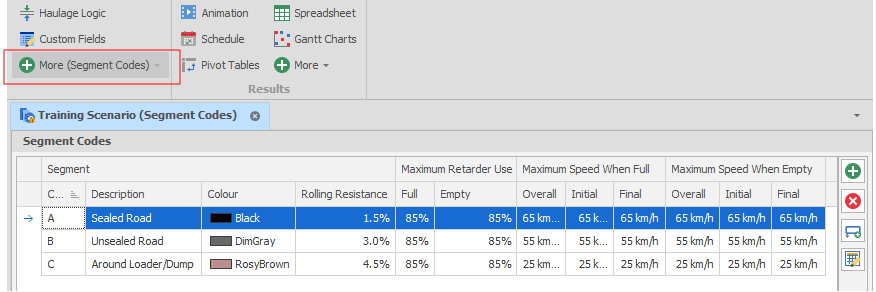
-
Return to the Scenario Settings and switch to the Haulage tab. Set a Default Segment Code (the most common Segment, usually what your established haul roads will be).
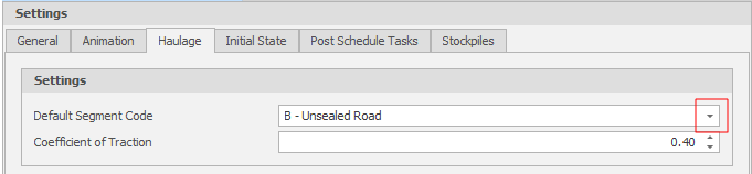
-
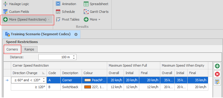
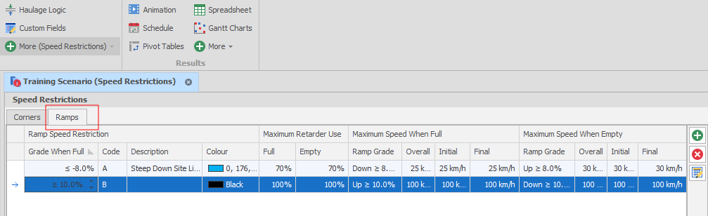
On the Home tab, in the Setup group: Select More > Speed Restrictions to add Corner and Ramp speed restrictions.
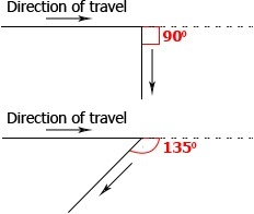
In addition to automatically calculated speeds generated from looking up the truck’s rimpull and retard curves, speed limits can be defined for both segments codes and also roads meeting certain criteria. These criteria include the grade of the segment (for ramps) and the angle change between two segments (for corners). Corners are applied to a change in angle between the original direction of travel and the new direction of travel illustrated in the image below:
On the Corners tab, the Distance element is how long the segment restriction will apply for (in total, not on each of the two parts of road involved).
On the Ramps tab, the Distance element is how long a segment on a ramp needs to be in order to have the restriction applied.
-
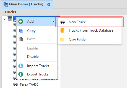
On the Home tab, in the Setup group: Select More > Trucks to add at least one Truck Type.
-
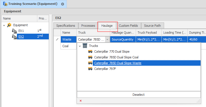
On the Home tab, in the Setup group: Select Equipment to apply Haulage Simulation to Equipment Processes:
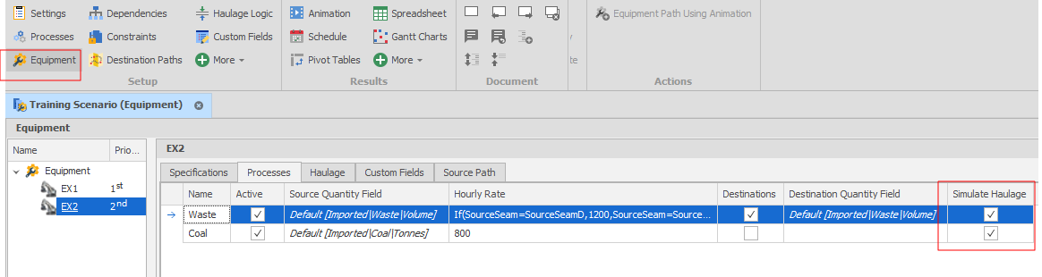
And set a Truck Fleet for each Equipment/Process combination:
Parameter Descriptions
Equipment (per process)
- Truck - Pick which truck fleet is applied for Raw Truck results
- Truck Payload - The amount of Source Quantity each Truck moves (uses whatever the Source Quantity unit of measure is)
- Loading Time - The amount of (static) time a Truck needs for Loading per cycle
- Dumping Time - The amount of (static) time a Truck needs for Dumping per cycle
- Queueing Time - Estimated Queueing time per cycle
- Additional Time - Any additional time to be reported differently
- Efficiency Factor - Increases cycle time to account for driver inefficiency
- Minimum & Maximum Trucks - Controls the truck fleet size. Effects discussed in the Results section.
Truck
- Apply TKPH Limits - Tick on to apply TKPH.
- 0% Engine Load Factor - Fuel use when truck is considered to be not moving. Includes Loading, Dumping, Queueing and Additional Time. (L/hr)
- 100% Engine Load Factor - Fuel use when truck is at 100% Engine Load (L/hr)
- Maximum Acceleration - Realistic limits 1.3-2.6 m/s2
- Maximum Deceleration - Realistic limits 0.9-1.8 m/s2
- Maximum Traction for Braking - Realistic limits 60-80%
- Empty Weight, Full Weight & Payload - Calculated (not changed). See Truck Axle for calculations
Truck Axle
- Number of Tyres - Affects various parameters. Should not require change.
- Full Weight - Change (reduce from manufacturer specs) to control under-loaded weight. See below for example
- Empty Weight - Change (increase from manufacturer specs) to control carry-back weight
- Driven - Affects various parameters. Should not require change.
- Tyre Rating - If TKPH is turned on, set the tyre TKPH for each Axle here
For example: The Caterpillar 789D has a maximum payload of 181 tonnes. After calculating a Waste Payload of 72 using bucket sizes, with a density of 2.4 tonnes/m3 the final Payload weight is 172.8 tonnes.
The Full Weight on each Axle of the truck should then be reduced to bring the total Payload to 172.8 tonnes.