Cut Blocks & Benches
![]()
Do the following:
-
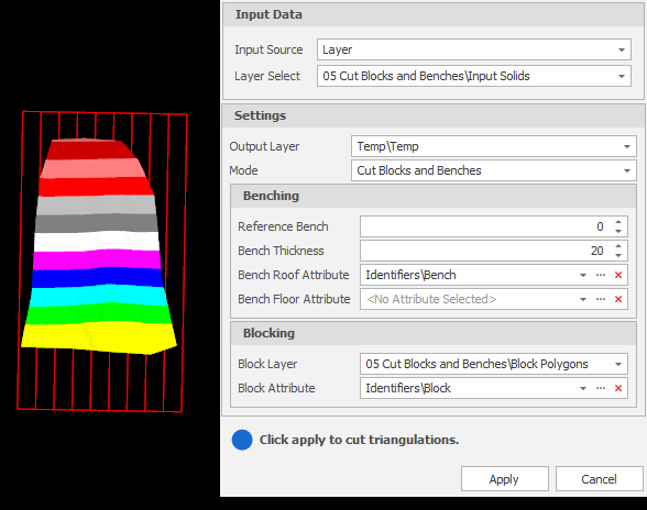
Select the Source of the data that will be used as input to the function:
Selection Design elements you have interactively selected in the Design Window. Visible Design elements that are visible in the loaded layer. Elements that have been specifically hidden are excluded. This a quick way of selecting all visible elements in a layer without having to explicitly select them. Layer One or more layers that you select. Names of layers currently loaded in the Design Window are shown in bold. For large datasets, you may prefer to select a layer rather than load that layer and select all of the elements in the layer. Selecting a non-applicable layer will have no effect. In most cases, an error icon
 will indicate the chosen input layer is not valid. Hover over the icon to view a validation hint.
-
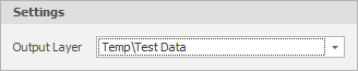
Use the drop-down to select an Output Layer.
Tip: In the Layer Selection pane, you can right-click on the Layers node (or a folder) to Add a new layer.
-
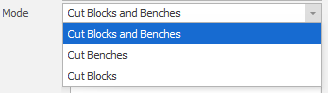
Choose a Mode and set the parameters for that mode. The dialog allows you to cut benches or cut blocks or both. If you are cutting blocks and benches, the Benching and Blocking processes are run in that order.
-
Finally click Apply to cut the triangulations based on the Benching and/or Blocking rules you have set.
Benching
Reference Bench
Specify a reference bench. Note that this is not necessarily the top-most or bottom-most bench. Any existing bench can be selected.
Bench Thickness
Specify a bench thickness. If you enter 20 metres, for example, every bench will be 20 metres apart.
Bench Roof or Floor Attribute
A bench that goes from zero to 20 metres is ambiguous - is it Bench Zero or is it Bench 20? Choose a Roof or a Floor attribute to remove any ambiguity.
Blocking
Block Layer
Select a layer containing the block polygons that will be used to cut the input solid(s).
Block Attribute
Each block polygon should have a unique Block attribute value. Select the attribute that will be used to identify which block each of the output solids comes from.